
Contents
- Introduction
- 1. Basic principles of CAD RI
- 2. Design efficiency modular cutting tool on the basis of established relationships of design and technology solutions
- 3. Status and development of projection subsystems CAD RI
- References
Introduction
Intensive development of engineering and technology in the late XX century , rapidly changing range of products , the appearance of the CNC and GAP , the creation of new structural and tool materials leads to the necessity of improving the design of cutting tools . High performance , flexibility, quick change , constancy of geometrical parameters - quality meet the requirements of modern production - lead to the replacement of the composite instrument teams. Payment instrument with all of the parameters and the selection of optimal parameters is complex, time-consuming task that is extremely difficult to produce manually. Therefore becoming increasingly popular computer-aided design of the cutting tool.
1. Basic principles of CAD RI
In the last two decades are becoming increasingly popular computer-aided design . Such systems can significantly reduce the design and commissioning of a wide range of products: from architectural design to chip topology . CAD systems allow to solve a variety of tasks , and are used in various industries . In particular, the two most common mechanical CAD types : system design process , and a solid modeling system . Recent studies allow for strength analysis and design details of assemblies and mechanisms at the design stage , as well as the right to make corrections in the course of analysis.
To date, developed in several areas of solid modeling systems. Listed below are the most common:
CAD-system - designed for direct creation model.
CAE-system - designed for automated calculation details.
CAM-system - designed for automated control of writing programs for CNC machine tools.
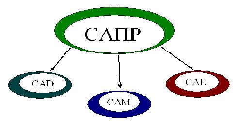
Figure 1 - Variety CAD
Computer-aided design occupy an exceptional position among computer applications - is industrial technologies aimed directly into the sphere of the most important areas of material production.
Over the past twenty years, computer-aided design tools have evolved from relatively simple drawing systems to integrated software systems that provide unified support the development lifecycle, from conceptual design to production preparation, testing and maintenance.
Modern CAD ??systems not only provide an opportunity to reduce the period of the introduction of new products, but also have a significant impact on the production technology, allowing to improve the quality and reliability of products, which ultimately determines its competitiveness. It is difficult to imagine today's industrial enterprise or design bureau , which would not be found any more computers and software , working in the field of automation. Design systems across the enterprise abroad is usually determined as CAD / CAM / CAE systems, in which the functions of the automated designing distributed as follows: modules CAD (Computer Aided Design)- for geometric modeling and computer graphics ; Modules CAM (Computer Aided Manufacturing) - for technological preparation of production ; modules CAE (Computer Aided Engineering) - for engineering calculations and analysis in order to verify the design calculations . Thus , current systems are able to provide automated support for the work of engineers and specialists at all stages of design and manufacturing.
Russia has traditionally existed division design problems on design, technology and design. Systems providing full automation of the entire process proekirovaniya or any of its stages, called automated systems l irrigation project lrovaliya (CAD).
Most fully the requirements and nature of modern CAD systems of highly integrated meet specialized systems developed within a single methodology. From this perspective, many of the current systems are not computer-aided design , so to speak , with a capital letter , but only "blanks " on the basis of which should be created (or already partially created) specialized systems for various applications and level. Such an approach is provided in many modern developments , however, the instrument of their specialization are languages ??like C + + or internal languages ??, and to access only basic functions and geometric graphics core , without the possibility of information integration and rejection of the established system of the kernel.
2. Design efficiency modular cutting tool on the basis of established relationships of design and technology solutions
Currently one of the most pressing problems facing manufacturing are cost savings and increased productivity, metalworking, raising the technological level and competitiveness of metalworking equipment and cutting tools. One of the main ways to reduce the cost of production is to increase the productivity of machining operations by increasing the cutting speed and the use of more advanced designs of cutting tools.
High speed cutting technology has several significant technical advantages in comparison with traditional , this - increase the proportion of material removal per unit time , and therefore increase operation efficiency and productivity ; reduction in cutting forces , heating and deformation of the workpiece , thereby increasing the machining accuracy of non-rigid parts; improving the quality of the machined surface ( high precision when setting the tool may receive a high- quality machined surface 11a to less than 0.5 microns ) , and others.
In today's production from an economic point of view in some cases beneficial not replace not yet obsolete (morally or physically), but do not provide the required accuracy or performance expensive equipment, and equip it with new tools and equipment.
Current state and prospects of development of metalworking characterized by extensive use of modular cutting tool (RIS ) equipped with interchangeable mechanically fixable cutting elements made ??of hard alloys , ceramics and superhard materials or polycrystalline inserts, or to have a diamond coating . Most widely used are the following tools with mechanical fastening cutting elements : turning communicating , scoring , cutting, boring and machine knives, circular drills , end and end mills , broaches and other external tools , basic dimensions are standardized.
Figure 2 - The tool with indexable inserts
(animation: 10 frames, 5 cycles of repetition, 160 kilobytes)
Variety of processing conditions and the lack of development of computational methods that do not allow to solve the problem of choosing a rational design tool at the design stage, led to the creation of a large range of single-purpose tool.
The rapid growth of information technology and market-oriented adaptation of production caused the development and implementation of computer-aided design ( CAD) software and systems through design - manufacturing (CAD / CAM) assorted cutting tools , most of which focused on the design of any type of instrument , its specific design or a structural member for the production of specific conditions , based on mathematical models which are used , constructed using different approaches , resulting in lost correlation tasks continuity models , and making the data , which leads to reduced quality of the design and production of conflicting solutions.
Thus, the current task is the development of a generalized system design modular cutting tool , developed using a systematic approach to the formalization of processes and systems RIS CAD and CAD / CAM RIS obeying uniform system simulation object capable of supporting conceptual unity of the models used , taking into account the factors of random processes metalworking and fuzziness initial data for designing to automatically construct an algorithm design tool based on some knowledge of the laws of its functioning, to create a single environment for a wide range of tasks , reduce development costs and research systems design teams cutting tools.
3. Status and development of projection subsystems CAD RI
Projecting CAD subsystem RI are the basis of development in computer-aided design tool production. Automated systems for technological preparation of production the most preferred is the use of hardware that allow for the design tool interactively. In this case, you can design the optimal design tool.
For any kind of cutting tool projecting subsystem developed in the following sequence: preparation of general methodological principles of design; description of the parameters of workpieces; compilation methodology for calculating the parameters of structural elements of the cutting tool (process parameters, etc.); testing of flowcharts calculation procedure; Determination of the composition and functions of the software modules; program development tool for calculating the parameters (process, etc.).
Fundamental to the creation of highly effective system design is to determine the correct information structure of the instrument. To CAD RI could operate in a mode to develop an optimal design should be disclosed following links:
- Prosgranstvennye defining the place and (sequence arrangement of individual elements (eg, the main gauge and cutting edge, liner, etc.);
- Functional defining parameter values ??(for example, the parameters of structural elements that provide sufficient strength and rigidity);
- External, because of the nature and conditions of interaction tool with the workpiece.
External relations determine the formation of the original data. Cutting tool works in certain conditions characterized by cutting modes, used coolant, equipment used, etc. The number of external factors reaches several tens, and so they should be grouped. There are three groups of factors. The first characterizes the workpiece and defines the relationships between the workpiece directly n tool. It includes:
- Chemical, physical and mechanical properties of the material of the workpiece;
- The roughness of the treated surface;
- The accuracy of the workpiece;
- The geometric shape of the workpiece;
- Method of obtaining details of the workpiece;
- Main dimensions and box office details;
- Additional data.
The second group of factors relates directly to the instrument itself. It includes:
- Design features of the instrument;
- Basic dimensions of the tool;
- Tool material;
- Need peretachivaniya;
- Especially heat treatment methods and wear-resistant coatings on the work surface;
- Additional data.
The third group of external factors include the operating conditions of the cutting tool:
- Cutting conditions;
- The nature of production (single, serial, etc.);
- Type of coolant and way to approach it in the cutting zone;
- Regulation of the tool life;
- Form and the need for removal of chips;
- Type of equipment on which you intend to use a tool;
- Additional data.
From the above software modules in terms of formalization of greatest interest is the program "material." In choosing the material of the cutting tool is not possible to establish certain mathematical relationships. Solving the problem of choosing the material was implemented in the form of a relational database, the formation of which is described below.
Identify external and internal communications at axial tools allows to consider 20-30 factors influencing the structure of CAD axial cutting tools, of which a considerable part of the effect on the choice of the tool material . But consider all the factors is impractical , because the practical use of complicated CAD RI due to the increase of the necessary basic data , as well as difficult to consider a number of factors ( application of emulsion , coating , etc.) due to the lack of experimental data. Therefore, more rationally allocate determinants .
In choosing the material for axial tool determining factors are:
1) the material of the workpiece;
2) the nature of preliminary preparation details, indicating the status of the workpiece surface;
3) the diameter of the hole;
4) cutting mode;
5) type of production parts;
6) the type and degree of automation equipment;
7) rigidity of AIDS;
8) features technological process of the tool-workpiece;
9) The availability of this tool material.
These nine factors are necessary for sufficiently informed choice of the tool material and partially take into account other factors that are not included among the nine. Each factor is invariant. Usually invited to select from 10 to 200 marks materials for machined parts. If the card selection is made for a particular company (industry), the number of marks should be limited to the needs of the enterprise.
Work will be carried out in the program PowerMill. PowerMILL is the basic software package in line Delcam. PowerMILL is designed to develop control programs for 3-axis and multi-axis CNC milling machines.
This program fits well with many CAD systems through Delcam Exchange, which generates a great many formats desired. Works especially well with a batch module Delcam PowerSHAPE, the system introduces the concept of Total Modeling, which allows a single simulation environment to combine different modeling techniques.
For ourselves PowerMILL interesting for the design and manufacture of prefabricated axial tools, already ready for 3D models made in CAD ??systems. Appointed by the finished model desired tool paths, cutting data, and all the necessary parameters.
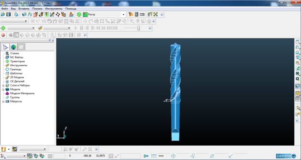
Figure 3 - Working in PowerMILL.
It should be noted the powerful and convenient means you modify the generated trajectories. In other CAM systems prevalent ideology of creating the next UP: first create all constraints , approaches , waste, further run - payment and get ready trajectory. At this stage, the result is either to accept or to start all over again. PowerMILL system provides a means for further work on trajectories. Initially, it suffices to define the basic parameters : type of strategy , step , and if necessary, and direction. Very rich base approaches waste stepovers and TP.
In general, it all depends on your own imagination (within reason ) and experience. Just easily create borders processing zones , and within the boundaries of reckoning reliably safe from desperately.Usually technologist works with the already established nomenclature , and someone to fill its own database actually used tools . For this purpose we developed a database consisting of PowerMILL Utils. The user can fill the base own instruments , asking not only tool geometry and patron , but also cutting regimes applied to different materials and machines. The disadvantage of this method is that the description of the tool in PMUtils somewhat different from the description tool in PM, as the interface and form . It turns out that PMUtils limit your ability to task the tool options .
However, when changing the tool designs have to change all the text of the program, and it is long and not user-friendly. Way out of this is to create macros for individual instruments and its trajectories.
References
- www.prorobot.ru/referats/r16/prorobot.ru-16-0010.doc
- Ю.Е. Петухов: Некоторые направления развития САПР режущего инструмента// СТИН. 2003. № 8.
- Ю. А. Новосёлов: Проблематика автоматизации проектирования режущих инструментов// СТИН. 2008. № 9.
- Петpушин С.И., Баканов А.А., Махов А.В., Геометрический и силовой анализ сбоpных свеpл со сменными многогpанными пластинами/Технология машиностроения, Вып. 10(64), 2007. – С. 27 – 30.
- Основи теории проектирования осевих комбинированных инструментов : дис. … дтн : 05.03.01 / Малышко Иван Александрович. – Донецк, 1995. - 419
- Проектування комбінованого осевого інструмента : метод. вказівки / сост. Кіселева І.В. – Донецк : ДонНТУ, 2007. –54с
- Основы САПР. (CAD/CAM/CAE.)/ Кунву Ли – 2004. – СПб.:Питер. –560с
- Сахаров Г.Н. Металлорежущие инструменты./ Сахаров Г.Н. Арбузов О.Б., Боровой Ю.Л., Гречишников В.А., Киселев А.С. – М.: Машиностроение, 1989. – 328 с.