
Abstract
Content
- Introduction
- 1. Relevance of the topic
- 2. Study ways to reduce energy consumption VMVM
- 3. Critical review and analysis of existing automation systems main fans
- 4. Investigation of the control system performance of the main mine fan installation
- Conclusion
- References
Introduction
Because of the limited space and shallow depth, underground workings susceptible to the accumulation of various hazards of natural and manmade, which in turn inevitably affects people in mining. This leads to a deterioration in working conditions, to a deterioration of the health of workers, diminished opportunities of manufacturing processes. Therefore, one of the most important parts of a complex technological system of mine ventilation system is mine workings, the task is to fight in the harmfulness of underground mines—they are fed into the development of liquefaction of fresh air to acceptable concentrations. From reliable uptime ventilation systems depends entirely on security, and often the lives of people working in the mine. Due to the availability of a safe mine conditions, the necessary power and control source strength of air movement as the main source of these forces used fan. In particular, in the mining industry to drive fans serving mine goes up to 8-10% of the electricity consumed by all mine. Therefore, the creation of high-efficiency fans and their proper use is of great economic importance.
1. Relevance of the topic
The task of automating mine ventilation is reduced to the filing and distribution to develop such a quantity of air, at which the predetermined performance faces, comply with the requirements of the Rules of safety and hygiene standards are maintained and optimal modes of fan installations. Features underground excavation technology minerals push this task to the most complex problems of mining. Difficulties solutions due to the following reasons: a)significant variability topology and parameters of mine ventilation networks, as well as the general interdependence of processes controlling the flow of air to the workings; b)complex and even contradictory dynamic connections between input to the amount of air supplied to the face, and a plurality of output parameters of the object to be controlled—the concentrations of methane, carbon dioxide, dust, etc.; c)the nature stohaticheskim aerogas processes and the presence of emission in the random function of adjustable parameters; d)the dispersal of large and significant number of sensors used to control the parameters of the mine atmosphere that move after slaughter, making it difficult to obtain accurate and complete information; d)the complexity of constructing a system of automatic control of the fan (main, flanking and local ventilation) while ensuring high standards given their reliability.
Figure 1 – Mine ventilation network (animation: 3 frames, duration: 55 ms, size: 150 kb)
2. Study ways to reduce energy consumption VMVM
Let us consider the main ventilation fan installation(VMVM) mines. It consists of the production and backup fans attached to them, the input and output elements, supplying channel diffusers, silencers, inlet portion and auxiliary devices for switching and reversing the air flow. It also includes installation of building motors with the ballast control equipment, remote control and automation. Studies conducted NIIGM im.M.M.Fedorova show that is currently in the coal mines of Ukraine is in operation 600 Byrne, of which 56 % consists of units with centrifugal fans and 44%—with the center[1,2].
Analysis of the development of coal enterprises of Ukraine allows to believe that due to the increasing depth of mining operations and, accordingly, increase drag workings proportion Byrne with centrifugal fans will increase. On the basis of this paper to consider accepting installation with centrifugal fans. Currently in operation is 340 units with centrifugal fans. Most installations consists of the two fans, but there are one unit with a spare motor and fan. 665 of the centrifugal fan 425 units (64%) can be categorized as modern. However, this does not mean that all these fans operate economically. A significant number of Byrne, who work outside the workspace with low efficiency or in the workspace, but with a significant excess power required to supply the mine installed air. This situation is due to several reasons as follows:
a)have changed since the characteristics of ventilation networks;
b)the poor state of the channel, the sealing elements of buildings;
c)in some cases the wrong type of fan selection for specific conditions;
d)lack of automation tracking varying parameters of the ventilation network and fan settings for operation with a maximum efficiency of the installation.
Analysis of Byrne with centrifugal fans shows that the excess power consumption is 17,450 kW. The most powerful energy consumers are big fans with impeller diameter of 3.15 m and above. They accounted for 91% of energy loss. On average, one plant has a capacity exceeding 370 kW. Because of differences actual characteristics of fans and ventilation networks mines annual electricity cost overruns main ventilation centrifugal fans is more than 170 million kilowatt/hour.
The decrease in energy consumption can be carried out in the following areas:
a)the introduction of a complex of organizational and technical measures aimed at maintaining a normal state of the elements associated with the installation and its building structures;
b) carrying out modernization fan installations and use of effective ways to adapt them to the parameters of ventilation networks.
Consider in more detail the second direction, it can be implemented by the following actions:
a)changes in the family characteristics of the fan:
1)changing the speed of impellers by replacing the drive motor with a different speed;
2)replacement of impellers;
3)isolation of the impeller;
4)changes in the number of impeller blades for axial fans;
b) setting a regular fan on the time-varying parameters of the network for the purpose of setting a maximum Efficiency and providing the necessary supply air amount due to the frequency or the drag regulation.
Best results are achieved when used in combination step and stepless. Need to change the characteristics of the family of the fan can not occur more than once every few years, thus should be conducted appropriate studies and subsequent modernization installation. Regular fan setting on the network settings must be carried out at intervals of several hours to several days. Such management requires constant monitoring either by staff or in the implementation of an automated tracking system and stabilize the performance of the fan. To determine the criteria for the management of ventilator consider installing fan operation on the network. Fig.2 shows a perfect operation, with the following notation:
h-depression;
Q-performance;
Qnr-the required performance.
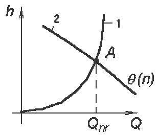
Figure 2 – The perfect fan operation network
Since the calculated value of the site is made Qnr VTB (ventilation and safety) on a quarterly basis, we assume that within three months Qnr value remains unchanged. Thus resistance mine network remains unchanged. Then at the exact (single) setting fan network at any one time a real fan operation will be as shown in Fig.3.
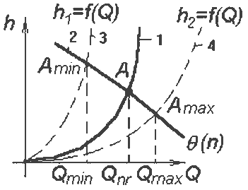
Figure 3 – Real fan operation network
Main tasks of the research:
Curves 3 and 4—the characteristics of the ventilation system, which can be obtained, respectively, at maximum and minimum flow resistance network for a period of three months. Thus in the absence of performance stabilization mode operating point A in the process of randomly moves along the curve 2 (the aerodynamic characteristics of the fan) from the point of Amin, Amax to the point, with the capacity of the fan will change from Qmin to Qmax, and Qmin less Qnr, contrary to Regulation security (PB). To avoid violations of the PB in the mine accepted mode shown in Fig.4.
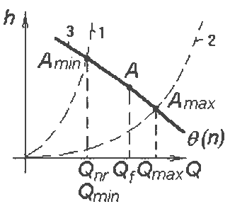
Figure 4 – Mode fan network to meet PB
3. Critical review and analysis of existing automation systems main fans
The main task of regulating mine ventilation is to maintain a predetermined amount of air in the mine ventilation network by varying the fan in accordance with the consumption of a certain volume of air. To do this, equip the mine ventilation equipment capable of ensuring the mine air to the working staff could freely without oxygen deficiency, perform manufacturing process mining and liquefaction hazards for fresh air to develop. To automate the main fans of mine equipment is widely used UKVG, ERVGP-2 ADSHV and Ukawa-2, which was produced by domestic plants on a large scale. Currently, for this purpose industry produces specially designed equipment for the coal industry UASHV: UASHV-1, and a versatile set for any fan of automation industries, ncluding mining, Ukawa-M.
1. Equipment UKVG
Designed for control of mining telemechanical main ventilation fans with electric motors, high and low voltage, as well as to monitor their work, if the unit contains no more than two fans. The equipment provides: remote control two main fans; remote reversing air flow fans; local management and fans lyadami; protects the motor from working in the asymmetric modes; zero protection of electric motors; dvuhpredelny automatic control and developed a continuous recording of the fan performance and depression; automatic light and sound alarm at start and stop the fan, overheating the motor bearings or the fan, change the fan performance and depression.
2. Equipment ERVGP-2
Equipment reversible main fans intended for remote control reversible two-stage axial fans: VOKR-1.8; WATER-11; WATERS-16 with electrical high and low voltage. ERVGP equipment-2 allows remote control of fan installation with low-voltage and high-voltage induction motors with squirrel or a wound rotor, as well as low and high voltage synchronous motors.
3. Equipment ADSHV
Designed for remote centralized control of mining fans with asynchronous motors of low and high voltage. The equipment provides: selective centralized control 12 fans-to 6 main and 6-12 downhole; remote reversing air flow fans; remote opening and closing of the duct; local fan control; local governance and lyadami vanes; protects the motor from working in single-phase mode; zero protection; control over the mode of operation of air handling units, selective control of depression developed by the fan; control of the correct selection of a fan; automatic continuous alarm ( light and sound ) alarm when any fan malfunction, short circuit of the air stream, failure of electric drive motor bearings overheating the fan is turned off local fan, power failure, failure of the election and control equipment parts; acontinuous recording of the performance and depression created main fan installation; telephone communication between the fan unit and the control station; a power failure in the area without stopping downhole fan.
4. Wheel unified automation equipment main fans Ukawa-2
The payload Ukawa-2 is designed to automate the fan systems equipped with one or two fans of any type. The equipment is based on the electromagnetic relay contactor elements consists of automation devices and electrical power. Kit allows you to: choose the type of fan control setting; work in normal and reverse modes; automatic control of unit operation in automatic and semi-automatic modes; private capacity control by turning the fan blades of the machine on the move; dim backup fan (on tripping working fan); Automatic load low voltage; autoreclosing Short (up to 10) disconnect the supply voltage; reversing the air flow without stopping centrifugal fan; sequence start the wheels of the first and second stages, or start one of the counter-rotating fan wheel; Capacity control of the fan by changing the rotational speed of the drive motor. You can connect to a set Ukawa-2 fan speeds using dual service car or asynchronously-valve cascade. Emergency shutdown occurs when the fan installation: short circuit and overload the drive motor; earth fault current carrying parts; synchronous motor work in asynchronous mode; disconnect the power supply to no more than 10 seconds, and its subsequent recovery; applying the brakes during the work; increasing the temperature of the motor bearings and fan above acceptable limits. The automatic control modes and parameters: acceleration of the engine; Ladi provisions; position guide blades; depression and fan performance; power failure at management stations; stator current of the drive motor; flow and oil pressure in the lubrication system; voltage to low voltage auxiliary electric buses; the fan stops.
5. Equipment UAVSH
Provides remote management and control of mining and non-reversible reversible fans with low voltage electric. Industry produced two versions of hardware UAVSH: UAVSH-1 to control the fan setting at a distance from it to the dispatch center to 10 km and UAVSH-2 at a distance of the control point up to 2 km.
4. Investigation of the control system performance of the main mine fan installation
Consider the method of controlling the output of the fan settings with the automatic control system (ACS). To do this, imagine a block diagram of our SAR performance of the fan(VU), composed in the mathematical package MATLAB, Figure 5.
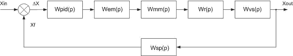
Figure 5 – a block diagram of an automatic control system (ACS) performance fan installation
In the block diagram presented: Wpid(p) — transfer function of the PID controller; Wedv(p) — transfer function of the electromagnetic component of the engine; Wmdv(p) — transfer function of the mechanical component of the engine; Wred (p) — transfer function of the gear; Wvu(p) — transfer function of the fan unit; Wdp(p) — transfer function of the sensor performance. ATS fan unit operates as follows: Uf voltage corresponding to the actual performance of the fan is compared with the setpoint Uz, and the difference between these voltages is the task for the regulator. Then the PID controller generates a control signal and acts on the engine fan blades guiding unit installation. Application of PID allows регулироватьпроизводительность due to exposure to the guiding unit fan motor. As a drive for rotating blades of the fan is considered asynchronous motor type 4A100L3U3. The transfer function of the motor is divided into two components:
1. Transfer function of the electromagnetic component of the engine.
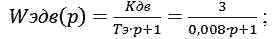
where CDW — transfer coefficient of the engine, CDW=3; Te — Time constant of the electromagnetic component of the engine, with Te=0.008 s;
L2`` — equivalent to the reduced inductance of the rotor winding. L2``=0,000637 ; R2` - reduced resistance of the rotor. R2`=0,079 ohms; Then Te=0.008 s. The transfer function of the mechanical component of the engine. Wmdv(p)=1/(Tmp+1)=1/(0,0586p+1); where TM—mechanical time constant component of the engine,with Tm=0.0586 s. Then Wmdv(p)=1/(0,0586p+1).
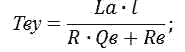
J—moment of inertia of the motor. J=0,1 kg×m2; ω0—synchronous angular velocity dvigatelya.ω0=149.73 rad/s ; Mp.f.—A dummy value of starting torque. Mp.f.=255 N×m; The transfer function of fan installation is as follows: Wvu(p)=Kwu/(TSS×p+1); Kwu where—coefficient fan installation Kwu=30; TSS—time constant fan installation, TSS=0.384 s; TSS=(La×l)/(R×QB+Rb); La=2461,12 ns2/m5 - acoustic mass production area; l=800 m — length of the output; R=56,4×10³ ns2/m5 — aerodynamic resistance network; QB=0 m3/s — performance fan ; Rb=56,4×10³ ns2/m5 — internal resistance of the fan. Transfer function of the gear in the simulation, we simulated using the rate of change of the limiter signal "RateLimiter", which sets the level of speed limit increase signal 20 s. The transfer function of the sensor performance is as follows: Wdp(p)=1/(TPD×p+1); where CTF=0.001 — the time constant of the sensor performance. The transfer function of the PID controller has the form: Wpid(p)=(β(Ti×p+1)(Tg×p+1))/(Ti×p). Given an automatic settings PID we obtained the following values of the time constants: Tg=0—ime constant of the differentiating component of the regulator; Ti=0.0102 s — time constant of the integrating component of the controller. The simulation results are shown in graph transient on Figure 6.
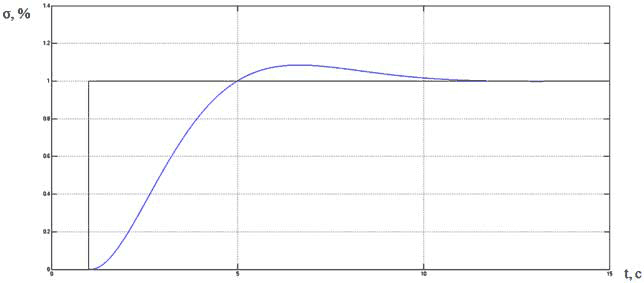
Figure 6 – The transition process automatic control system (ACS) performance fan installation.
Upon receipt of the transition process, we obtain the following information: the amount of overshoot is not more than 9 %, and the transient time is 12 s. Po these data we can say that our SAR is effective to achieve the best performance of the fan installation.
Conclusion
Currently such automated systems Byrne stabilization performance is not generally available. This leads to the fact that the amount to compensate for variation of the supply air fan systems operate with high performance, and therefore—to the overrun of electricity; In addition, unanticipated violations ventilation regime lead to failures in the process mined. Thus, the development and implementation of an automated stabilization performance fan unit to the setting for the maximum Efficiency will ensure a reliable, sustainable and cost-effective ventilation of mine workings with minimal deviation from the preset mode that can only be achieved under automatic control, quickly eliminate gassed workings and reduce downtime winning machines on the gas factor, to create conditions to increase the maximum allowable concentration of methane, reduce obscheshahtnoy required air flow and power consumption due to air distribution and management of main fans (AIV) in economy mode. All this will increase the safety of mining operations and provide certain economic benefits.
At this point in the diploma writing process and in connection with this information this essay is not complete and will soon be changed, supplemented and edited.
References
1. Батицкий В. А., Куроедов В. И., Рыжков А. А. Автоматизация производственных процессов и АСУ ТП в горной промышленности: Учебник для техникумов. 2-е изд., перераб. и доп. – М.: Недра, 1991.—303 с.
2. Гаврилов П. Д., Гимельшейн Л. Я., Медведев А. Е. Автоматизация производственных процессов .М.:Недра, 1985.-215 с.
3. Автоматизация и автоматизированные системы управления в угольной промышленности / Под ред. Б.Ф.Братченко – М.: Недра, 1976. – 383 с.
4. Черных В. «Simulink: Инструмент моделирования динамических систем». [Electron sourse] – Accend mode: www.exponenta.ru
5. Братченко Б. Ф., «Стационарные установки шахт». – М. «Недра», 1977.–440 с.
6. Толпежников Л. И. Автоматическое управление процессами шахт и рудников: Учебник для вузов.2-е изд., перераб. и доп.—М.: Недра, 1985.—352 с.
7. Автоматизация технологических процессов угольных шахт /Мелькумов Л. Г., Лазукин Н. Я., Богопольский Б. Х., Розенберг Р. Л.—М.: Недра,1973.—352 с.