
Summary on the theme of master’s work
Abstract
- Introduction
- 1. Relevance of the topic
- 2. Objective and research problems
- 3. A review of research and development
- 3.1. Analysis hydrotransport mine complex as an object of automatic control. Management criteria and requirements for automatic control system
- 3.2. Development of a mathematical model of the automatic control system of hydrotransport mine complex
- 3.3. Study of the automatic control system of hydrotransport mine complex
- 3.4. Rationale of the block diagram of the automatic control hydrotransport mine complex
- Findings
- References
Introduction
At present, the technical means algorithms are developed and compiled basic production management program designed for mechanical means of excavation and transport efficiency of coal. Application of the mines hydraulic means excavation and transportation of coal, which differ in principle from mechanical works, requires special tools and algorithms for management of such facilities [1].
As the experience of hydraulic mines of Donbass and Kuzbass, in hydraulic mines can be effectively applied hydraulic and mechanical method of coal extraction: mechanical - using shearers and hydraulic - using jetting. In this case, the transportation of coal mining on the surface of the mine faces carried a combined way - from mining sites with coal shearer recess via belt conveyors, and from mining sites with hydraulic coal mining - hydraulic transport.
Absence or insufficient knowledge about many aspects of the theory and practice of jetting and automation of mining operations at hydraulic mining were the basis for selecting the topic of master’s work.
1. Relevance of the topic
Efficient management of hydrotransport mine complex can be evaluated to ensure the continuous operation of the mine complex hydrotransport under slurry flow deviation from the calculated values at the minimum required flow rate of water and electricity for 1 ton of transported rock mass. Therefore, the development and study of automatic control systems of hydrotransport mine complex is a hot topic.
2. Objective and research problems
Objective: Improving the efficiency of complex hydrotransport mechanical-hydraulic mine with coal extraction method by study parameters and control algorithms developed on basis of the automatic control system of hydrotransport mine complex.
To achieve this goal it is necessary to perform the following research objectives:
1. Analyse hydrotransport mine complex as an object of automatic control and management to formulate criteria.
2. Develop a mathematical model of the system of automatic control of hydrotransport mine complex.
3. Surveys of the automatic control system of hydrotransport mine complex.
4. Substantiate and develop a block diagram of an automatic control system of hydrotransport mine complex.
3. A review of research and development
3.1 Analysis hydrotransport mine complex as an object of automatic control. Management criteria and requirements for automatic control system
Hydrotransport mine complex with mechanical- hydraulic coal extraction method is designed for transportation of coal and water pumping and how to control consists of a number of local facilities management (see figure 1): gihydrolift installation (GPI), carrying out transportation of slurry from the sump to the surface mine (SM); coal pumps installation (CPI), for transfer of slurry from the mining sites with hydraulic coal mining in the sump gIhydrolift installation; conveyor belt that transports the coal from the mine site to combine and coal mining; dewatering unit (VU), carrying out pumping water mining mine site with coal shearer recess in the sump gihydrolift installation.
Figure 1 – Hydraulic circuit hydrotransport mine complex: 1 – pumping station, 2 – drainage installations, 3– pulpovodosbornik, 4 – gihydrolift, 5 – to the concentrator, 6 – run unconfined hydrotransport 7 – crusher, 8 – conveyor, 9 – from pumping stations (animation: 11 shots, 5 cycles of repetition, 129 kilobytes)
Also in figure 1 shows a non-pressure hydraulic transport route, which dropped from a coal conveyor through the crusher and simultaneously fed water per flush from pump unit (OU) from the surface of the mine. Next, the slurry enters the free flow in the sump gihydrolift installation. Thus, in the hydrotransport mine complex output of one local object is the input of a subsequent object, interconnected unity process. Also characteristic feature of complex hydrotransport mine is uneven traffic coming to it, due to coal mining technology in the faces [3].
To ensure efficiency and rhythmicity work hydrotransport complex mine management to exercise such an object on a two-tier management system, on the upper level which the coordination of the process units of the complex, and at the bottom - control of individual process units. Management at all levels shall be in accordance with the terms of management criteria.
Global criterion for coordinating the work of hydrotransport mine complex generally formulated as: ensuring continuous operation hydrotransport mine complex in the conditions of the slurry flow deviation from the calculated values at the minimum required flow rate of water and electricity for 1 ton of transported rock mass. The requirement for continuous availability of hydrotransport dictated by the random nature of the complex needs of hydropower and receipt rock mass transported from the network faces. The requirement for the minimum required water flow in the system due to the need to ensure hydrotransport: maximum efficiency of processing units, the minimum operational costs for maintenance hydrotransport complex and maintaining maximum bandwidth for its rock mass. Requirements minimum required power consumption due to high energy process plants, since as the drive motors and pumps used powerful coal pumps from 630kW to 1500kW motors. Since hydrotransport mine complex consists of a set of technological facilities, the conditions for a global test management is performed partly in managing complex each object according to local control criterion for this object.
Coal pumps installation is a node of concentration slurry with coal pumps (see figure 2).
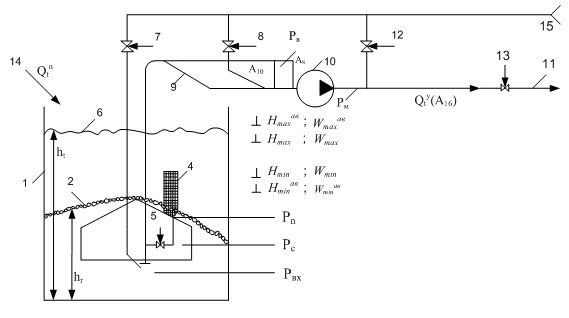
Figure 2 – Hydraulic circuit coal pumps installation: 1 – sump; 2 – storable solid; 3 – suction device (SD); 4 – line recharge; 5 – sliding adjustment; 6 – the level of the slurry; 7 – catch water; 8 – coal pumps fill valve; 9 – suction pipe; 10 – coal pumps; 11 – pressure coalduct; 12 – valve flushing; 13 – sliding discharge; 14 – the influx of non-pressure troughs hydrotransport; 15 – conduit
Perturbation (fluctuation inflow slurry from the bottom), it is governed by non-pressure channel. Coal pumps installation with respect to the perturbation behaves like radiant link, and in relation to manage impacts - as inertia. Lag period (mode switching) up to 10 minutes or more. Its capacity of the sump a insufficient to compensate for possible disturbances.
For coal pumps installation local criterion management Ф1 (Тэ) can be represented as:
where: Wmin, Wt, Wmax – respectively, the current amount of filling, the upper and lower value of the regulatory (working) capacity of the sump, m, Tэ – efficiency of the determination period, modify, Wp* – volume effectively used part of the regulatory capacity Wp of the sump, characterizing the amplitude of fluctuations in the level (level), m3, Δ Wp inefficiently used part Wp due to the maximum value of the absolute error of the accepted method controlof the coal pumps installation, m3.
Controlled variable is the filing of coal pumps installation, which depends on the current operating mode (deregulation, regulation). Flow of slurry from the coal pumps installation load for subsequent link hydrotransport mine complex - gihydrolift.
For gIhydrolift installation criterion management Ф2 (Тэ) can be represented as:
where: Wminг, Wtг, Wmaxг – respectively, the current amount of filling, lower and upper values of the working capacity of the sump of gihydrolift installation;
Qminу, Qtу, Qmaxу – minimum allowable current and maximum possible feed coal pumps of gihydrolift installation. Qminу is determined by calculating: speed above the critical rate of rise in Qminу ≤ Qtу, Qmaxу determined by the maximum possible number of working coal pumps providing efficiency limit value of coefficient of efficiency.
Control of the gihydrolift installation in accordance with the specified criteria can be implemented as a set of control by working coal pumps (load on gihydrolift), and by controlling the supply of coal pumps.
Local criterion for controlling the supply of water in the unconfined track hydrotransport Ф3 (Тэ) can be represented as:
where: Qmin, Qminв – actual and minimum required water flow, m3/s,
Value Qminв defined by the formula:
The minimum required amount of water supplied for non-pressure hydraulic transport in running the conveyor line is determined by the formula:
where: Qm – conveying capacity flow m3/s; ρ – density of water, kg/m3; qв – specific water consumption m3/kg.
The specific water consumption is defined as:
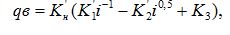
where: Кн – coefficient accounting mistakes laid gutters; Кн = 1,2 - 1,5; Кі – empirical coefficients depending on the properties of the material being conveyed, their values for the most common conditions hydromines given in the relevant tables [1].
The minimum amount of water needed for flushing off the tape after the troughs of the conveyor line is determined as:
where: τminn – the minimum time needed washing slurry pipeline, s.
Lтр – pressureless length tracks, m; Vкр – critical velocity of hydrotransport m/s.
Thus, the essence of controlling the water supply in the non-pressure hydraulic transport route is to ensure a minimum number of the driver supplied for unconfined hydrotransport a running conveyor belt and ensure minimum required washing time when disconnecting track tape conveyor line with subsequent trip pump station PS [5].
Drainage installations is not hydrotransport installation, it is designed to pump water from the mining sites with coal shearer recess in the sump of gIhydrolift installation that affects the ratio of S:L slurry, and hence the efficiency of the gIhydrolift installation. Also drainage installations is a major consumer of electricity and has a free cycle of technological interruptions that allows to combine work with periods of slave electricity tariff restrictions on mine daily time interval (during peak periods), that is used as a dewatering unit consumer regulator is a power that essential [2].
Thus, the local criterion control the drainage installation Ф4 (Тэ) can be represented as software schedule drainage installation only outside peak periods. In the peak period before the sump of drainage installation must have the free volume of water that, when switched off, drainage installation header accumulated water from mine workings. In the work [2] describes how to install a sump automatic control based on peak periods in the power supply system of the mine: a way to force the inclusion of time, followed by regulatory filing, the control method on three points and a way to force the inclusion time. For conditions hydrotransport mine complex method may be used for compulsory inclusion of time, which is used in the control algorithm pumping station automation equipment type VAV.1M.
3.2. Development of a mathematical model of the automatic control system of hydrotransport mine complex
As shown by studies of hydrotransport mine complex can be in one of three states:
1. Deregulated S1 – the coal sump installing setting slurry pumps with a nominal supply Qymax.
2. Overregulated S2 – the coal sump installing pumps water at a reduced supply Qymin.
3. The coal sump installing is off S3.
Each state Si has its time Ti transition to the next state:
Control period τy of the coal sump installing setting determined by the expression:
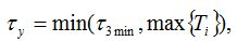
where: τmin – minimum possible delay of transport flows in unconfined the sump of the coal sump installing.
The numerical value τзmin is determined from the expression:
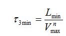
where: Lmin – length of the track to the unconfined hydrotransport to the sump; Vnmax – fastest possible free flow of slurry.
Control action is necessary to work with τ ≤ Ti and when the volume filling of the sump Wτ one of its limit values (Wmax, Wmin). For the case when τ3max < max { Ti } below is a calculation of the corresponding setpoints, which adjust margins.
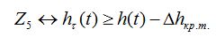
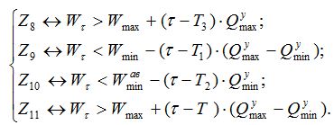
We pose the following set of auxiliary logical variables that take part in the formation of an array of control commands:
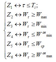
After prolonged use the coal sump installing in state S2 level of the stored in the sump can reach the critical value. The critical level is such that the above the coal sump installing unable to dispense solid and water in the required concentration for hydrotransportation. Critical level generally depends on the location of the camera feeding suction device, and the volume of the pump. Critical level may be solid even at the difference between the level of the slurry hτ(t) order Δ hкр.т. = 0,1-0,3 m. In line with this logic is formed variable reflecting the fact of the formation of the critical situation:
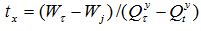
Further, management the coal sump installing should provide stabilization level within the specified limits for the cases of short-term fluctuations Qtn, excess supply of coal pumps, with a mean inflow to the control period may not exceed Qy, provided that adequate computation load (Qn) and coal pumps productivity. In order to determine the moment of formation of the manipulated variable in the range of simulation τ ≤ τy must take into account the current level of filling the sump Wt and forecasted volume filling Wτ for this filing Qty, of the coal pumps, determine the time interval tx (at the end of interval τ), during which coal pumps must operate on a modified (required) filing Qty so that with respect to time Ti coal pumps to transfer the required amount of feed mode filling the sump until the end of the interval τ would meet the required limit values Wj
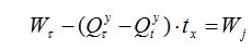
Whence
A moment of formation of the control action is determined by the implementation of inequality:
Thus formed variables Z1 ÷ Z11, in conjunction with the logical state variables Si carboniferous setting, the required set of functions of control actions:
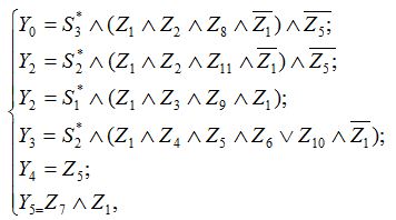
where: Y0 – command deregulate
, Y1 – command regulate
; Y2 – command off
; Y3 – command submit an emergency water to the sump
; Y4 – command off
; Y5 – command turn off the water in the rock faces
[6].
3.3 Study of the automatic control system of hydrotransport mine complex
As mentioned in paragraph 3.2 of one of the functions of automatic control system of hydro-mine complex is to regulate the feed of the coal sump installing. At this time, known the following control methods regulate the feed of the coal sump installing [2]:
1) regulation without prior transfer of coal pumps on water;
2) regulation with advanced transfer of coal pumps on water.
The first group includes the following methods. Regulation by: change in speed of the impeller coal pumps; air inlet to the suction line coal pumps; throttling the penstock.
All of these methods in this group have a common significant disadvantage: they all depths for a given regulation require increased by the same value of the initial flow rate, which leads to a sharp increase in friction loss and a substantial reduction in the transport length. So marked ways do not meet modern requirements for effective operation the conditions for the coal sump installing.
Method of controlling the preliminary coal pumps transfer the water. Designed in the STI (now called the University Donetsk National Technical University).
This method is based on the use of the suction device 5 and is provisionally translation coal pumps for water transport pipeline full flushing at maximum flow through coal pumps the water contained in the sump station, followed by the standard pipeline throttling valve. Application of this method showed sufficient efficiency regulation. Thus, in the work, accepted method for automatically controlling the supply of the coal sump installing by adjusting valves on the pipeline, which pumps. Before adjusting the feed of the coal sump installing installation translates to pump water using a special suction device.
Simplified diagram of the coal sump installing setup is shown in figure 3. On the pipeline that pumps installed controlled valve.
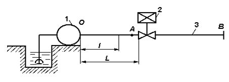
Figure 3 – Simplified flowsheet of the coal sump installing
Closing or opening controlled latch 2 is replaced by resistance network aQ2, whereby changes characteristic of pressurized pipeline.
Figure 4 shows the characteristics of the coal sump installing in regulating feed coal pumps changing the position of the valve in the pipeline, which pumps. The slope of the pressure characteristics of the pipeline HТП determined by the resistance of the pipeline a.
The more controlled valve is covered, the more resistance the pipeline (a3>a2>a1), and the steeper the network performance will be held. Changing the characteristics of the pipeline (HТП1 → HТП2 → HТП3) leads to a change in the operating mode of the coal sump installing.
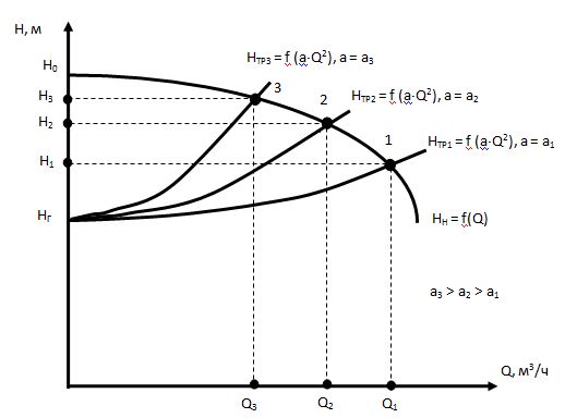
Figure 4 – Characteristics of the coal sump installing in regulating feed coal pumps changing characteristics of the pipeline pressure
Block diagram of the automatic control system feed of the coal sump installing setup is shown in Figure 5.
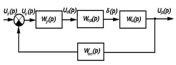
Figure 5 – A block diagram of the automatic control system feed of the coal sump installing
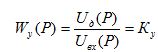
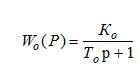
The transfer function of the circuit power
has the form:
The transfer function of gate drive circuit:
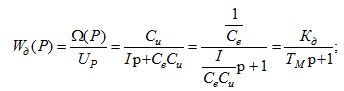
Control object - the valve disclosed aperiodic chain with transfer function:
The simulation SAR, using parameters of the coal sump installing type U900-90, equipped with a latch type ZGP250 drive PEG100, found that the ACS does not satisfy the conditions of operation: dynamic deviation is 45%, the duration of the transition process with tпп = 1,12, the error is ± 7%. Therefore, the structure of the ACS introduced the corrected circuit. Figure 6 shows a block diagram of an automatic control system the corrected filing of the coal sump installing.
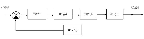
Figure 6 – Block diagram of the corrected, the automatic control system of the coal sump installing
The transfer function of the corrected closed system looks like:
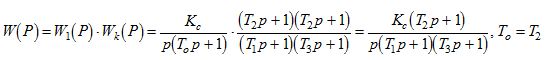
where: Wк – the corrected transfer function circuit.
As a result, studies have provided graphic transition in ACS of the coal sump installing. (see figure 7, where the curve 1 - transient uncorrected ACS and curve 2 - transient-corrected ACS).
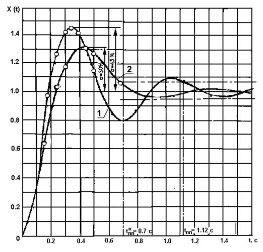
Figure 7 – Graphs of the transition process in ACS of the coal sump installing
As can be seen from the graph, the transition process uncorrected ACS (curve 1) is characterized by dynamic deviation equal to 45 %, the duration of the transition process tпп = 1,12 with system error ± 7%, that does not satisfy the conditions of operation. Introduction correction link reduces pressure change valves in 2,21 times (see curve 2) that is
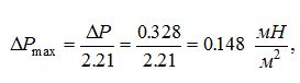
which is a percentage of the nominal
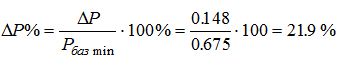
Duration of the transient process tпп = 1,2 satisfies the conditions of exploitation, thus correcting system ACS indicator of tппк = 0,7 s. will satisfy these conditions.
3.4 Rationale of the block diagram of the automatic control hydrotransport mine complex
For automatic control of hydrotransport mine complex in accordance with the criteria proposed two-tier control of computer-integrated control system using fieldbus control system structure.
Management system refers to the classification of control systems to PLC-system [8]. At the top level management is operator workstation of hydrotransport mine complex (OWS) is a personal computer station OWS provides the following functions:
- coordination of complex process plants of hydrotransport mine complex in start-up mode, operating mode and stop;
- the timing of the transfer of process plants hydrotransport mine complex power-saving mode based on peak loads in the power system of the mine;
- predict the state of the water level in the sump drainage installation, slurry in the sump of the coal sump installing and gidrolift installation;
- processing and display in tabular and graphical form in the form of interactive graphics on dispatching equipment, monitor or display panel of hydrotransport complex mine operator the following information: the current water level in the sump drainage installations; the current level of the slurry in the sump of the coal sump installing; the current level of the slurry in the sump of gidrolift installation; work and pumping the coal sump installing (on, off); pumping of the coal sump installing; emergency condition and drainage installations the coal sump installing deciphering the type of fault; current energy consumption and bilge the coal sump installing; installation work of the coal sump installing overregulated or misalignment modes; assembly line work (on, off); availability of water supply to the washing away of coal in non-pressure hydraulic transport route;
- maintaining a database of information technology, its archiving and backup;
- generate reports on the operation of the hydrotransport mine complex;
- remote control duty and standby pumps, coal pumps, valves (on - off).
НOn the lower level controls are programmable logic controllers (PLC1–PLC4) for managing a particular technological installation, sensor units (SU1–SU4) and block of executive mechanisms (EM1–EM4) (see Figure 4). To ensure spark protection industrial PLC controllers applied intrinsically safe isolating converters (SIC).
Physical and logical connection between industrial controllers and OWS station in a single system process control management of of hydrotransport mine complex provides industrial network, for example, Profibus [7].
PLC1 controller is used to control the coal sump installing and performs the following functions:
- switching on and off the coal sump installing on a particular algorithm depending on the level of the slurry in the sump or on command from station WOS system;
- ensuring continuous operation of the coal sump installing with uneven admission in the sump slurry coal pumps work by transferring the water from the slurry;
- control the level of the slurry in the sump filing of the coal sump installing pressure in the discharge line, bearing temperature of the coal sump installing aggregate consumption, the load on the drive motor;
- providing hydraulic and electrical protection of the coal sump installing;
- transmission and reception of information from the station WOS;
- the coal sump installing feed control unit (provided automatic control system ACS).
PLC2 controller is used to control the gidrolift installation and performs the following functions:
- switching on and off gidrolift installation on a particular algorithm depending on the level of the slurry in the sump or on command from station WOS system;
- ensuring continuous operation of the gidrolift installation with uneven admission in the sump slurry coal pumps work by transferring the water from the slurry;
- control the level of the slurry in the sump filing of the gidrolift installation pressure in the discharge line, bearing temperature of the coal sump installing aggregate consumption, the load on the drive motor;
- providing hydraulic and electrical protection of the gidrolift installation;
- transmission and reception of information from the station WOS;
- indication of modes of the gidrolift installation of the PLC and other automation hardware.
PLC3 controller is used to control the drainage installation and performs the following functions:
- flow alarm when the drainage installation is turn;
- switching on and off the drainage installation on a particular algorithm depending on the level of the slurry in the sump or on command from station WOS system;
- automatic fill the drainage installation before inclusion;
- management of the drainage installation, taking into account periods of tariff restrictions electricity mine on a daily time interval;
- control the level of the slurry in the sump filing of the drainage installation pressure in the discharge line, bearing temperature of the coal sump installing aggregate consumption, the load on the drive motor;
- providing hydraulic and electrical protection of the drainage installation;
- transmission and reception of information from the station WOS;
- indication of modes of the drainage installation of the PLC and other automation hardware.
PLC3 controller is used to control the supply of water in the unconfined hydrotransport track and performs the following functions:
- opening and closing valves on the pipeline supplies water to flush the rock mass, which comes off the assembly line in track unconfined hydrotransport;
- formation delay for flushing the route unconfined hydrotransport when you turn off the conveyor line;
- transmission and reception of information from the station WOS;
Findings
The analysis hydrotransport mine complex as an object of automatic control global criterion formulated management of hydrotransport mine complex - ensuring continuous operation hydrotransport mine complex in the conditions of the slurry flow deviation from the calculated values at the minimum required flow rate of water and electricity for 1 ton of transported rock mass. Since hydrotransport mine complex consists of a set of technological facilities, the conditions for a global test management is performed partly in managing complex each object according to local control criterion for this object. Therefore, in the criteria are formulated as local control of the coal sump installing, drainage installations and installation of water supply to the track hydrotransport unconfined.
In work the mathematical model of the automatic control system of hydro-mine complex, which is based on the fact that hydro-mine complex can be in one of three states: deregulated, and regulated with the coal sump installing setting is off. he resulting mathematical relationships forming control actions for each state of the complex with the time of transition from one state to another local management criteria for the coal sump installing, drainage installations and installation of water supply to the track hydrotransport unconfined.
Compiled a block diagram of ATS and mathematical modeling. As a result, studies have provided graphic transition in ATS of the coal sump installing. The obtained parameters satisfy ATS operation.
For automatic control of hydrotransport mine complex in accordance with the criteria proposed two-tier control of computer-integrated control system using the fieldbus. At the top level management is operator workstation hydrotransport mine complex. On the lower level controls are programmable logic controllers for specific technological installation, sensor units, power actuators and intrinsically safe isolation transformers to provide intrinsically safe industrial controllers. Formulated by means of automation functions of each level of management.
When writing this abstract master’s work is not finished. Final completion: December 2014. The full text of the work and materials on the topic can be obtained from the author or his head after the specified date.
References
1. Груба В. И., Папаяни Ф. О., Никулин Э. К., Оголобченко А. С. – Основы управления гидроэнерготранспортными системами., – Донецк: Донбасс, 1993. – 225 с.
2. Данильчук Г. И., Шевчук С. П., Василенко П. К. Автоматизация электропотреблениия водоотливных установок – К.: Техника, 1981. – 102 с.
3. Коденцов А. Я. Гидротехнология на шахтах. – М. Недра 1984. – 320 с.
4. Світлий Ю. Г., Круть О. А. Гідравлічний транспорт твердих матеріалів. – Донецьк: Східний видавничий дім, 2010. – 268 с.
5. Груба В. И., Борисов А. А. Алгоритм комплексного оптимального управления гидросистемой шахты // Разработка месторождений полезных ископаемых. – Киев: Техника, 1973. – № 31. – с. 26–29.
6. Груба В. И., Папаяни Ф. О. Усовершенствованный алгоритм управления технологическим процессом гидрошахты. // Горная электромеханика и автоматика. – 1981. – вып. 39. с. 41–47.
7. Мячев А. А. Интерфейсы систем обработки данных: Справочник / Под ред. А. А. Мячева. – М.: Радио и связь, 1989. – 416 с.
8. Иванов Ю. И., Югай В. Я. Интерфейсы средств автоматизации: Учебное пособие. – Таганрог: Изд-во ТРТУ, 2005. – 252 c.