
Abstract
Content
- 1. Justification themes and names of relevance
- 2. Possible results to be expected in the performance of work, their novelty and significance
- 3. Analytical review
- 3.1 Impact mechanisms that implement the elastic energy of the solid body
- 3.2 Ударный механизм, реализующий энергию гидростатического давления жидкости в скважине
- 4. Impact mechanism that implements energy hydrostatic fluid pressure in the well
- list of sources
1. Justification themes and names of relevance
Program development of mineral resources base of Ukraine for the period up to 2030 requires an increase in the volume of drilling exploratory wells. In some situations in wells used devices operating cycles which implement unsteady fluid motion (drums arrangements, pulsating pumps, etc.).
To date, most of the mathematical models of cycles of these devices is based on the Bernoulli equation for unsteady fluid motion. However, these models are of limited use. More accurate results provide models that are based on a system of equations IA Charny. Therefore it is necessary to determine the scope of these models and to assess their accuracy for different operating conditions downhole devices.
More precise mathematical description of workflow technology can help improve the use of these devices and optimize their design parameters for different operating conditions.
Therefore, the study of cycles devices unsteady motion of the fluid in the well based on various theoretical models is an urgent task.
Communication with academic programs, plans, execution of work on the application of scientific institutions or industrial organization.
Work performed at the request of the Company, LLC Yugovostokgaz
and associated with the implementation of the National Program for development of mineral resources base of Ukraine for the period up to 2030 (Act of 21.04.2011 № 3268-VI).
Objective - improvement devices unsteady fluid motion in the well (the hammer mechanism and pulsating pump) based on a study of their cycles on various mathematical models.
Research objectives:
- Explore the duty cycles of devices with the unsteady motion of the fluid in the well (the hammer mechanism and pulsating pump) based on the Bernoulli equation.
- Explore the duty cycles of devices with the unsteady motion of the fluid in the well (the hammer mechanism and pulsating pump) on the basis of a system of equations Charny.
- To compare the results of the job description of cycles performed on different models and to determine the boundaries of their application.
- Develop recommendations for the use of devices with the unsteady motion of the fluid in the well (the hammer mechanism and pulsating pump).
The idea of work – different approaches to describe the cycles of devices with the unsteady motion of the fluid in the well (the hammer mechanism and pulsating pump).
object of study - device with the unsteady motion of the fluid in the borehole.
subject of research - duty cycles of devices with the unsteady motion of the fluid in the well (the hammer mechanism and pulsating pump).
2. Possible results to be expected in the performance of work, their novelty and significance
New results:
- Mathematical models of cycles devices unsteady motion of the fluid in the well (the hammer mechanism and pulsating pump) based on the Bernoulli equation.
- Mathematical models of cycles devices unsteady motion of the fluid in the well (the hammer mechanism and pulsating pump) on the basis of a system of equations IA Charny.
- Recommendations on the selection of design parameters and application technology devices with unsteady fluid motion in the well (the hammer mechanism and pulsating pump).
Value of the work is:
- In determining the application of mathematical models cycles devices unsteady motion of the fluid in the well (the hammer mechanism and pulsating pump) based on the Bernoulli equation and the system of equations IA Charny.
- In developing recommendations for the choice of design parameters and application technology devices with the unsteady motion of the fluid in the well (the hammer mechanism and pulsating pump).
Planned testing results (participation in conferences, filing papers for the contest, publication, filing for an invention, etc.)
Participation in Republican scientific conference of students Drilling
. Submission to the contest of student research works and the utility model application.
3. Analytical review
3.1 Impact mechanisms that implement the elastic energy of the solid body
ГThe hydraulic jars, charging which is carried out at a fixed (braking) of the striker by differential fluid pressure between the cavities movable devices are widely used in drilling for oil and gas and adequately covered in the literature and patent sources.[1, 2, 7]
More reliable of these jars are considered UMLP gated (GUM device firms Bowen
, Mason
, Houston Inzhenirs
, and others). Hydraulic jars open type (PT-146, PT-95), where the piston chamber is filled with flushing fluid to be less effective due to rapid abrasion device elements and the possibility of jamming the piston slurry material, but have a much simpler design.
Hydraulic hammer mechanism GUM (Fig. 3.1), designed VNIIBT designed to eliminate sticking drilling tool by striking aimed up or down (depending on the mechanism of assembly) [2]. Gum comprises a spindle 1, 2 and adapter 7, connected with the cylinder 3, which has two chambers of different cross-sections, the striker 4 and the piston rod 5 6 mounted within the cylinder 3 and connected with the spindle 1. Assembly device cavity is sealed and is filled with oil.
Upon liquidation of sticking gum combined with a shell and give emergency drill string tension force greater than its weight on 200-800 kN. First moving speed of the piston 5 will be small, since the pressure above the piston cavity is created at the overflow oil under the piston through the three throttle holes. Here the drill pipe is stretched by accumulating energy reserve. Coming in 213 mm, piston 5 falls into the cylinder 3 with longitudinal grooves. Since the cross-sectional area for the passage of oil above the piston cavity subpiston increased more than 200 times, the spindle 1, addicting pipes, which are compressed, and the striker moves up four hits on the inner face of the adapter 2. This impact is transmitted through the cylinder stuck tool and 3 adapter 7. For application re-strike spindle 1 is lowered down, creating an axial load of 10-20 kN.
If the gum to be used to strike down its disassembled, invert cylinder 3 with a piston 5 by 180 degrees and again collected. After connecting mechanism stuck column unload drill pipe by the amount of weight collars. After entering the piston 5 in wide cylinder chamber 3 oil pressure mechanism decreases and falls UBT hitting end sub ??spindle 1 to 2 subs. This impact is transmitted to the stuck tool.
At this time, GUM - one of the most reliable and efficient domestic jars. He gives a good effect on the Elimination of wedging caused by foreign objects fall into the well, sticking cuttings puffs in the gutter. However, experience in the application of the mechanism shows that its operation in high temperature wells (at a temperature of over 140 degrees) is impractical.[8]
When troubleshooting stuck due to adhesion to the filter cake on the short length, it is recommended to apply the GUM two assemblies, one of which is supposed to strikes up, and the other - down.
To strike down the drill string in the layout should be UBT whose weight exceeds the weight of the projectile stuck no less than 25%. When hitting up the amount of deformation of the UBT should provide drill pipes 400-500 mm. When drawing pipe less than 300 mm work GUM ineffective.
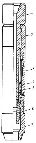
Figure 3.1 - Hydraulic hammer mechanism
Device [5], depicted in Fig. 3.1 refers to the hydraulic yasam open. It consists of a body 1 with an annular groove on the inner surface 2 of the spindle 3 and the hollow stem 4, made in the form of hexagon for transmitting rotation to the drill pipe to the housing 1. At the bottom of the stem 4 is made under the seat 5 with a throttle valve 6 channel 7, and also mounted striker piston 8, compacted cuffs 9 preloaded bearing ring 10. the connecting threads 11 at the bottom of the housing 1 is screwed check valve 12. piston rod 4 and 8 are radial passages 13 for communicating the rod chamber with the annular chamber 14.
Yas may be included within or drill down to the place of accident. The valve 6 is absent, which allows for flushing through the cavity rod 4. After resetting the valve 6 and landing in the saddle 5 pull the drill string. The rod 4 starts moving up, the check valve 12 is closed and the liquid from chamber 14 through ducts 13 and the throttle passage 7 flows into subpiston chamber body 1. Due to the pressure drop in the channel 7 of the drill string stretching occurs. Once the piston 8 will go into annular groove 2, flushing fluid flows freely from the upper chamber to the lower housing 1.
Force which inhibits stem 4, disappear, and the latter, being dispersed by a sharp contraction of the pipe string, a powerful blow to the striker piston-8 on the inner projection of the housing 1.
For the next impact tool fed down. The flushing fluid flows freely in this mechanism between cavities. Upon reaching the stem 3 lowermost position again allowed tension drillstring and the cycle repeats.
The advantages of this mechanism are as follows:
- The simplicity of design and operation;
- Possible inclusion in the shell, which improves the efficiency of emergency operations;
- Impact to the bottom of the washing agent and the possibility of other operations to eliminate sticking (eg installation of bathrooms, etc.).
At the same time, the apparatus has disadvantages open jars.
Hydraulic jar original design [9],established in Ivano-Frankivsk Oil and Gas Institute. This device is an open area affects stuck and powerful tool connects shock pulses with a sharp decrease in the static level. Furthermore, when the first attack, the zone is isolated from sticking drilling fluid column in the borehole. Thereby increasing the efficiency of removing the shell sticking to the filter cake.
3.2 Impact mechanism that implements energy hydrostatic fluid pressure in the well
UMLP this type have not yet found widespread use. In the previously created devices for releasing stuck projectile used Hydroshock phenomenon that occurred when filled with liquid evacuated chambers. These mechanisms differed low efficiency, because they were single action (for recharging was necessary to pull them to the surface).
The composition UMLP -89 (Fig.3.2) includes a body 1 with a rod 2. Rod 2 has an anvil 3 and a septum 4, which is installed between the piston and the firing pin 5. To the housing 1, which has the shoulders 6 for cooperation with the striker 5 are side hole 7, performing the role of the management body and are designed to provide connectivity subpiston camera to the annulus. In the lower part of the housing 1 is mounted coupler 8 having a spline connection with the lower part of the stem 2, which ensures transmission of torque from the drill pipe connected to a housing for screwing on the stem with the stuck UMLP projectile. 4 placed under the partition check valve 9 for connecting the camera to a well subpiston as the piston moves down 5 - striker. In the stem 2 and a check valve 10 to disconnect the cavity of the drill string and the annulus.
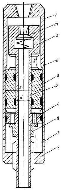
Figure 3.2 - ULP-89
The device operates as follows. After an accident UMLP descends into wells filled with liquid, and installed over the stuck part of the drill. The check valve 10 prevents flow while flushing agent of drill pipe in the well, which remain partially empty or filled (based on fortress tower collapse).
Therefore, the device is maintained above the piston chamber pressure, significantly smaller than the wellbore. Then one body rises to align the side holes 7 subpiston area. Fluid flow from the annulus underneath the piston-guided impact body 5 by moving the latter upwards. At endpoint, it strikes the anvil 3 transmitted through the rod stuck tool 2.
To re-strike the device returns to its original position. Wherein the drill string is lowered. The shoulder of the housing 1, with the piston contacting the striker-5, the latter moves down to the partition 4. When the liquid is displaced from the subpiston chamber into the borehole via a check valve 9 and the side port 7 occupy the position below the partition 4, blocking access to the solution subpiston chamber. The fluid pressure above the piston in the cavity and the well become the same as before use. Then the cycle can be repeated.
Compared with the known mechanisms of shock UMLP-89 has the following advantages:
- High energy performance at low cost drive power;
- By eliminating the participation of the column in the creation and perception of shock transmitted to the tack-welded shell, the increased reliability of the device and improve the operating conditions of drill pipe;
- Due to efficient energy transfer at impact stuck tool in deviated wells expanded scope UMLP;
- Occurs when the mechanism sharp local pressure drop in the accident zone can increase the likelihood of liquidation sticking due to the pressure difference between the well and the reservoir;
- Possibility of regulating the energy parameters within wide limits;
- Simplicity of design, installation, repair and security applications.
Aforementioned advantages indicate the prospects of ULP-89 while eliminating sticking in exploratory wells diameter 76-93 mm and more. However, this device can not be used in wells with low washing liquid.
4. Designing devices to eliminate sticking of the drill
At the Department of technology and engineering drilling DONNTU involving author has developed a new scheme of the device to eliminate sticking of the drill, which received a patent for utility model.
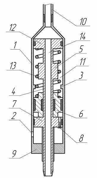
Figure 4.1 - Diagram of the device to eliminate sticking of the drill
A device (Fig. 4.1) consists of a housing 1 with radial holes 2 and the step 3 on the inner surface of the hollow shaft mounted concentrically with the anvil 4 and 5 the hammer - piston 6 positioned in the annular space between the housing 1 and the stem 4, below the anvil 5 for rigidly 4 is connected to a rod baffle with the non-return valve 7, 8. at the bottom of the housing 1 is configured adapter 9 which has a splined coupling with the lower part of the rod 4 to transmit torque from the drill pipe 10 to the piston rod 4. cavity above the piston 6, the striker is made as a low-pressure chamber 11 is isolated from the space of the drill string 10 by a piston 12 mounted freely relative to the housing 1 and rigidly connected to the anvil 5. low pressure chamber 11 is filled with air or gas therein and arranged a spring - elastic element 13. Hollow stem 4 and the space inside the drill pipe 10 are connected a channel 14 in the piston 12.
The device operates as follows.
It is included in the drill and set over coring set (not shown), which is the most vulnerable part of the projectile from the point of view of stuck. During the drilling torque is transferred from the drill pipe 10 to the piston rod 4 through an adapter 9 which has a splined coupling with the lower part of rod 4, and the axial load is transmitted to the bottom due to the interaction of the upper body 1 with a piston 12. Flushing fluid passes into column-set through the channel 14 and the cavity of the rod 4.
Figure 4.2 - Operation is to eliminate sticking of the drill
Figure animated. volume - 83.2 kb.; number of frames - 5; time delay - 0.5 s.; reps - 7.
In the case of sticking the core set (not shown) the body 1 is lifted by drill pipe 10 to a compound of two radial holes housing 1 with a cavity between the piston, striker 6 and the partition 7. Due to the fact that the pressure under the piston, striker 6, the hydrostatic power pressure washing liquid column in the wellbore is significantly higher than the air pressure in the low pressure chamber 11 (equal to atmospheric pressure), the fluid flows out of the borehole under the striker piston 6 and moves it upward. Piston -peen 6 moves up, compressing the spring 13 and the air in the chamber 11 of the low pressure and hit the anvil 5, which is transmitted through the rod 4 is stuck on the column- set. With the ultimate speed of the piston 6 - striker, and, consequently, the impact energy is controlled by adjusting the stiffness of the spring 13 on the basis of the strength of the components of the device and threaded connections.
To return the device to its original position the drill pipe 10 and is fed downward by its own weight or by the action of the feed mechanism. When the housing 1 is moved downward and the shoulder 3, which is in contact with the piston, striker 6 moves downwards. The liquid from beneath the hammer-piston 6 is displaced into the well bore through the check valve 8 and the opening 2 that at that moment occupy a position below the partition 7. Thus the spring 13 returns to its original position. Further work cycle is repeated.
Application of the device allows you to strike when a fault occurs in the well without additional preparatory operations by constantly maintaining a low pressure in the cavity above the piston-striker.
This master's work is not completed yet. Final completion: December 2014. The full text of the work and materials on the topic can be obtained from the author or his head after this date.
list of sources
- Булатов А.И., Аветисов А.Г. Справочник инженера по бурению. В 2-х томах. Том 1.-М.:Недра,1985.-382 с.
- Гидравлический бурильный яс. Международная заявка 84/00577 РСТ МКИ4 Е21В 31/113 / Дж. Ньюмен; Опубл. 16.02.1984.
- Каракозов А.А. Ударные механизмы для ликвидации прихватов бурового снаряда в разведочных скважинах. В кн.
Пути повышения эффективности геологоразведочных работ: Тезисы докладов научно-техн. конференции
Научные разработки - геологоразведчикам региона
.- Днепропетровск, ДГИ, 1990.-С.37-38.- Гидравлический ловильный яс для применения в скважинах, снабженный последовательно расположенными поршнями. Заявка Великобритании N 1959401 МКИ4 Е21В 31/113 НКИ E1F; Опубл. 9.09.1981.
- Гидравлический яс. А.с. 1078028 СССР E21B 31/113 / Червинский В.П., Абрамов В.Б., Филев В.Н. и др.;Опубл. 30.01.1984, БИ N4.
- Гидравлический яс. А.с. 13646992 СССР МКИ4 Е21В 31/113 / Каранда С.И., Мерянов В.К., Басов Н.И.; Опубл. 7.01.1988, БИ N1.
- Гидравлический бурильный яс. Международная заявка 84/00577 РСТ МКИ4 Е21В 31/113 / Дж. Ньюмен; Опубл. 16.02.1984.
- Дубленич Ю.В., Жданков В.Ф. Определение области эффективного применения гидравлического ударного механизма для ликвидации прихватов бурильных труб / РНТС "Бурение".-Вып.4.-М.:ВНИИЭОНГ, 1979.-С.12-14.
- Устройство для ликвидации прихватов. А.с. 1330301 СССР МКИ4 Е21В 31/113 / Ясов В.Г., Андрийчук И.С., Аниськовцев А.В. и др.; Опубл. 15.08.1987,БИ N30.
- Горная энциклопедия [электронный ресурс]. — Режим доступа: Приведенно описание прихватов