
Abstract
Contents
- Introduction
- 1. Relevance of the work
- 2. Goals,tasks, object and subject of research, the idea of work
- 3. Analytical review
- 4. Rationale and direction of work
- 5. Description of the developed mechanism
- 6. The principle of operation of the developed mechanism
- 7. The possible results that are expected to apply when performing work, their novelty and value
- References
Introduction
State program for development of mineral resources of Ukraine for the period until 2030, planned increase of drilling exploration wells. But in the conditions of Donbass many wells cross intake formations that need DAB in the process of drilling to avoid big expenses in mud.
However, existing means plugging not always effective at the intersection of the unstable fractured rocks. This requires the development of new and improvement of existing technologies and technical means plugging exploration wells.
1. Relevance of the work
In mining are well known and widely used non-explosive depleting substances (NEDS), for example, on the basis of quicklime, which, by interaction with water considerably increases its volume. To obtain NEDS used quicklime, which is obtained in lime kiln at temperatures 1150–1350 °С.
Fundamentally these properties can be applied to cementation testing zones acquisitions exploration wells. It will allow to increase productivity and reduce the cost of drilling through more effective struggle with the absorption of drilling fluid.
Therefore, the development of new technologies plugging zones acquisitions exploration wells and technical means of its implementation is an important task.
2. Goals, tasks, object and subject of research, the idea of work
The purpose of work is development of technology of plugging exploration wells with the use of materials, expanding at interaction with the flushing liquid, development of construction of cement shell and formulation of grouting mixture.
Research objectives:
- Formulate the grouting mixture on the basis of materials, expanding at interaction with the washing liquid.
- To develop the design of the cement shell for use with materials, expanding at interaction with the washing liquid. Run 3D-simulation and design drawings developed projectile.
- To develop technologies plugging exploration wells with the use of materials, expanding at interaction with the washing liquid.
The object of the research is the process of plugging exploration wells.
The subject of research – technology plugging and formulation of grouting mixture on the basis non-explosive depleting substances.
The idea of work – application for increase of efficiency of struggle against absorption in exploration wells materials, expanding at interaction with the flushing liquid.
3. Analytical review
Plugging devices use or for delivery to the well plugging material prepared on the surface, or for making cement slurry directly in the well. These devices represent the capacity of the container and accessories, providing leak tightness design, retrieval and mixing of the components.
Cement shell design, V. A. Kichigina and A. A. Maryina
Cement shell of this design (Fig. 1) used for isolation of zones of absorption and installation of bridges in wells.
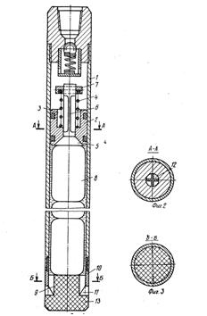
Figure 1 – Cement shell design, V. A. Kichigina and A. A. Maryina
It consists of a housing 1, 2 piston, which is made through axial channel under the non-return valve 3, which has a spring 4, closing element 5 and the rod 6 with lock 7. Closing element 5 is installed in the bottom of the piston 2 interoperable with lekarstvennymi containers 8, filled with dry backfill material. Check, that element is made with a diameter less than axial channel 9 10 Shoe that has knives 11. The shaft 6 is designed for horizontal drillings 12. Length exceeding the height of the piston 2. In the Shoe of a shell installed plug 13.
Cement shell works as follows.
At the wellhead casing 1 fill with fluid and down the containers with 8 pre-contracted to the desired density dry powder quick-setting cement material. After filling housing containers insert the piston 2 with the check valve to the end position of the last container. Then the projectile down on the pipe at the right interval well. Through pipes with a pump pump fluid into the Cabinet above the piston 2 and simultaneously rotate the cement shell. Under the pressure of a liquid piston 2 moves down, passing at the same time the pressure on containers with 8 backfill material and fluid in the body of the shell, so the containers are not deformed. After extrusion stub 13 projectile slowly rise up. Containers passing through knives 11, are cut, and backfill material gets rotational motion and intensively mixed with the liquid filling the full amount of the well, cavities and cracks. At the time the piston 2 to 10 Shoe and squeezing out the last of the container with backfill material valve moves down until it stops the release 7 in the piston 2, flowing liquid through grooves 12, available at stock 6, the pressure on the pressure gauge pump drops, which is a signal of the complete extrusion grouting material. After that the rotation of the projectile and the flow of the liquid stop. Valve 3 under the action of a spring 4 is returned to its original position. Then the same projectile produce seal been closed quick setting cement mixture in an absorbent layer.
The device allows to define precisely the completion of the process of complete extrusion powder quick-setting cement material, which at intensive hashing of liquid forms a homogeneous, uniform, with the same structural-mechanical properties of fast-curing stagnant mass, quickly gaining strength, forms high-quality insulation bridge. This is especially important in the fight against collapses the well wall, catastrophic and complete acquisitions drilling fluid. The device also allows plugging dry
wells, balance sheet and hydrostatic pressure of the liquid column in the rise of the projectile from the well.
However, this projectile has the following disadvantages: the inability to use, it can be seen in the small diameter wells due to the small difference of the squares of the piston and drill pipe.
Cement shell structure of A. S. Pakolchuk
Cement shell (Fig. 2) presents an elongated core pipe with taps and special spindle at the lower end. At the upper end of the outer tube is screwed adapter 2. At the lower end of the adapter has undercut which you want to insert the upper end of the inner tube. To seal the groove of the adapter is inserted a rubber gasket.
Outer and inner tubes cement shell made of several sections. The lower end of the outer tube is screwed to the body of the valve.
The body of the valve has four slots with 4 holes, designed to expiration of the accelerator setting. In the heart valve is the penetration hole widening at the bottom. In the case of valves is inserted 7 valve, which is mounted spreader 6 and four pin-valve. In the valve body is screwed mixer 5, with holes for entering into a well prepared mixture of fast-curing. In the centre of the mixer has a hole left-handed 8, which is screwed spindle with a Cam 14. Nut 11 prevent loosening of the spindle from the mixer. At the end of a spindle is mounted plug 10 from pins 12 and teeth 13. The purpose of the eccentric 14 is that when rotating cement shell to take the lower part of the spindle from the well axis and, clutching the well wall teeth, slightly slow down the rotation of the spindle, which is why last come unscrewed from the mixer up until nut 11 will not come to a stop.
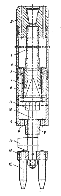
Figure 2 – Cement shell structure of A. S. Pakolchuk
Liquidation of absorption by means of cement shell of this design is as follows. In the threaded hole in the hull of the mixer is screwed spindle, at the upper end of which screw restrictive nut. The valve is then inserted into the body in this position the screw on the mixer. When rotating the left spindle comes inside mixer until then, until the pins-the valves do not block the vents valve sockets. When the pins will block valve, spreader only partially included in a tapered hole in the body of the valve, but will not block it.
At this Assembly mixing device of cement shell completed. Then in the body of the valve screw one or two sections of inner and outer tubes. As such, the projectile set on the clamps over the mouth of the well. Then in the tube cavity filled accelerator setting and screw the adapter. The upper end of the internal tube fits tightly into recess adapter.
The collected projectile lowered into the well and set on 1,5–2 m below the zone of absorption. For high quality quick-setting mixture it is necessary to start the expiration of the accelerator coincided with the arrival in the area of absorption of cement through the divider. Therefore, before the start of cementation calculate the capacity of the pipe.
Cement is pumped into the well until, until he is forced out from the column bars all mud and does not go to the divider. This moment is determined by the quantity of cement, pumped into a shell. As soon as the solution will be available for the divider, the column of bars with cement projectile result in rotation jerky. After 50–60 revolutions projectile slowly begin to rise up. During rapid rotation of the projectile spindle come unscrewed from the mixer and the divider together with the pin-valves goes down, opening up access to the accelerator coming into the mixer. The outflow velocity corresponds to the speed of the jet cement and regulated calibrated holes in the valve. The number and size calibrated holes are regulated depending on the pump performance. For pump GCP-200/40 and oil and gas fields-250/50 need 4 holes with a diameter of 10 mm.
The opening of the valve means the beginning of the expiration of the accelerator. After that, tamping projectile slowly rise up, freeing well place for a quick-setting mixture. The rise of the projectile be made at an average speed of 1,5–2,0 m/min.
By the time the remains of cement will go into the mixer, the projectile must be raised above the zone of cementation.
Cement shell design V. G. Asova
Cement shell design V. G. Asova differs from previous ones, in a single run of the tool allows you to make washing the wells exploited in the area of absorption inert fillers and quick-setting cement mixture. Shell (Fig. 3) consists of the external and internal pipe 2 5, the top 1 and lower 8 adapters, two centralizers 4 and 6, 7 nozzle and tubes 9 with the Central hole.
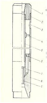
Figure 3 – Cement shell design V. G. Asova
Accelerator of hardening poured through the hole 3 and a shell immersed in the area of absorption. This is followed by flushing interval and alluvium fillers through the hole in the tube. Before injection of cement mixture in a column of drill pipes throw the ball, which covers the hole in the tube. The result is under pressure cement mixture tube is pushed out of the projectile, opening the annular gap between the nozzle and the adapter. Through the gap accelerator setting starts to arrive in the mixer and into the well, where is formed quick setting mixture. The width of the ring gap is regulated by screw the nozzle using the Allen key.
4. Rationale and direction of work
Now in mining actively using non-explosive depleting substances (NEDS), the essence of which is that they increase when interacting with water. This effect can also be used for filling of cracks in rocks, such as plugging intervals well. Preliminary experiments showed the practical ability to use NEDS for plugging zones acquisitions.
5. Description of the developed mechanism
Cement shell (Fig. 4) consists of a container 7, which contains elastic shell 5. Inside the elastic shell 5 posted by tamping material 2 (dry powder NEDS). At the bottom of the container 7 hosted the bottom 4, made of drillable material and knives 6. In the upper part of the cement shell made adapter 1, which is connected with drill pipes 8 lock 10. In the upper part of the container 7 installed piston 3 seal 12, connected to a container 7 shear pins 9. In the piston 3 made under saddle ball 11.
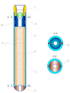
Figure 4 – Cement shell
6. The principle of operation of the developed mechanism
Cement shell (Fig. 5) is lowered into the hole on drill pipes 8, connected with them adapter 1 and lock 10. To bring the projectile in the action column of drill pipes 8, immediately before injection of drilling fluid, dropping the ball 11, overlapping channel piston 3. Creating pressure, by which cut off the pins 9. Piston 3 when it begins to push on elastic shell 5, bottom 4 is squeezed out of the projectile, and backfill material into the shell portnum 3 squeezed into the well, and the shell 5 rips knives 6.
Figure 5 – Cement shell in working position
Water softener mixed with powdered NEDS. Then penetrates the hydration reaction, which leads to increased NEDS and its penetration into the pores and cracks in the walls of the borehole. After hardening NEDS interval redrille. This absorption is liquidated, because the pores and cracks plugged.
5 frames, volume animation 100 KB
Animation 1 – Scheme of work of the cement shell
To obtain non-explosive depleting substances use quicklime, which is received by lime kiln at temperatures within 1150–1350 °С.
For the preliminary work will be used formulations non-explosive depleting substances, require in the mining.
In the future they will be refined based on the results of preliminary testing.
7. The possible results that are expected to apply when performing work, their novelty and value
New results:
1. Formulation of grouting mixture on the basis of materials, expanding at interaction with the flushing liquid.
2. Construction of cement shell for use with mixes on the basis of materials, expanding at interaction with the flushing liquid.
3. Recommendations on technology plugging exploration wells with the use of materials, expanding at interaction with the flushing liquid.
The value of the work is to determine the impact of the content of components in cement mixes on its parameters, development of technology plugging and cement apparatus for its implementation.
References
- Невибухова руйнівна речовина НРР–80: Патент України (на 20 р.) № 59940, С04В 24/00/ Грибко В. Ф.; Щебликін С. В.; Палей А. В. –Опубл. 15.07.2005, бюл. № 7.
- Багза М. И., Галазов Р. А., Крысин Г. С. Тампонирование скважин: Технология изоляции поглощающих горизонтов при бурении скважин. – Донецк: Донбасс, 1986.
- Юшков А. С., Серик Е. Л. Бурение геологоразведочных скважин. – М.:Недра, 1976. – 288 с.
- Ивачев Л. М. Борьба с поглощениями промывочной жидкости в разведочном бурении. – М.: Недра, 1982. – 293 с.
- Ивачев Л. М. Промывочные жидкости и тампонажные смеси: Учебник. – М.: Недра, 1987. – 244 с.
- Ивачев Л. М. Промывка и тампонирование геологоразведочных скважин: Справочное пособие. – М.: Недра, 1989. – 246 с.
- Юшков И. А. Тампонажные смеси: Учебное пособие. – Донецк: ДонНТУ, 2008. – 73 с.