
Abstract
- Introduction
- 1. The main part. Experimental studies
- 2. Processing of experimental results
- Conclusion
- References
Introduction
Among the services that provide network Ukrainian GNSS reference stations occupies a special place for the implementation of corrective information RTK - mode. Popularity RTK - amendments can be explained by the fact that users can directly in the field to obtain the coordinates of the points of interest. While users are provided with the correction information, as from a single base station network and formed by appropriate network methods. Network corrections let you receive the exact coordinates of vast areas, while avoiding the growth of position error with the distance from the base station. They created a special algorithm software ensuring network management center based on satellite data of all or several base stations at the time of the mobile satellite receiver. Knowing the exact coordinates of the base stations and the network using satellite data is continuously coming from these stations, program the control center via the ambiguity resolution algorithm cycles beats phases satellite signal is instantaneous residual coordinates for each of the stations. On the basis of these data using the Kalman filter model is constructed errors in determining the location in the network, which allows for the instantaneous state of the atmosphere, and clock error GNSS satellite orbits. This model is needed for the formation of differential corrections are common to all stations in the network. Network differential corrections transmitted to users in different types, which are used to calculate its exact coordinates of their location. [1].1. The main part. Experimental studies
Experimental studies were carried out to study the effect: configuration of base stations, the distance between adjacent base stations and the mobile device, and a method of forming RTK corrections for the accuracy of coordinate definitions positioning of users in the network RTK- mode. For this network segments were created, consisting of base stations installed in the settlements. When selecting areas for experimental studies took into account such factors as the existence of an open sky and a steady job GPRS link. Schematically the location of base stations forming cell and the mobile receiver is shown in Figure 1.

Figure 1 - Schematic arrangement of base stations and the mobile receiver: a) cell number 1; b) Cell number 2; c) Cell number 3;
(Animation: 8 shots, 7 cycles of recurrence, 57.1 kilobytes)
There are 4 types of formation of network RTK - amendments:
1. Flachen-Korrektur Parameter (FKP) or method of areal amendments. This method involves the calculation of differential corrections to the area covered by multiple base stations without the prior position of the moving satellite receiver[2].
2. Virtual Reference Station Method (VRS)
2. In this method, the current location coordinates of mobile satellite receiver previously discharged into the control center. Using these coordinates, the software creates a network control center differential corrections to the user about the virtual point in space, close to the point of the mobile satellite receiver at a given time, and sends it to the user[2].
3. MAX (Master Auxiliary Concept)
3. In this method, the server sends to the mobile control center satellite receiver data streams, including "raw" satellite observations and coordinates a network base station, called the master station, and the difference in values corrected after ambiguity resolution "raw" observations and coordinates other base stations in the network, with respect to data master station . Other stations are called auxiliary. Correction values are calculated on a mobile satellite receiver for what it must have the appropriate software . In a mobile receiver restores the corrected after ambiguity resolution "raw" satellite observations for all base stations in the network and identifies the exact coordinates of its location.[2, 5].
4. Method i-MAX (Individualized MAX)
4. In this method, the amendments to the user are relatively real, physically existing network base stations . In this satellite corrections are formed on the basis of base stations located in the cell network, fixed or created automatically by the control center after receiving the coordinates of your location mobile satellite receiver. Mobile satellite receiver receives individual amendments, subject to optimally selected stations in the network, based on the distance, quality and volume of satellite data currently[2, 4].
When performing experimental studies on GCP initially installed dual-frequency satellite receiver, which produced the accumulation of information in a static mode at least 4 hours for the geodetic reference point. With the accumulation of data in the internal memory unit has been configured as follows: recording interval - 5 sec., Mask angle - 10 degrees. Then on GCP made a series of at least 10 measurements while limiting each measurement time (15 periods) in RTK mode to obtain amendments on various technologies, namely MAX, i-MAX, FKP, Virtual RS.
Final analysis of the measurements carried out in laboratory conditions. Control points were determined by measurement of the accumulated post-processing relative to the nearest base station network. They were taken as reference and compared with the coordinates obtained by measuring RTK network mode.
2. Processing of experimental results
With the software LGO company Leica Geosystems mode pislyaseansnoyi processing performed calculation of reference point coordinates, which then produced RTK measurements. We determined differences in each coordinate component:
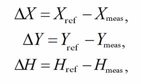
where Xref, Yref, Href - Coordinate reference value;
Xmeas, Ymeas, Hmeas – measured value coordinates.
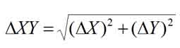
Discrepancy in terms of the measured and reference coordinate values calculated by the formula:
In addition, the calculated mean values for the coordinates of all the measurements and the mean differences were:
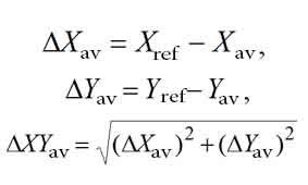
Also, the standard deviations were determined relative coordinates of the estimated mean values.
The table shows the results of the processing and analysis of measurements made in cells network number 1, 2, 3.
Table 1 - Results of analysis for determining the accuracy of the coordinates
| Тип використовуваних мережних поправок | The discrepancy at Хav, m | The discrepancy at Уav, m | The discrepancy at XУav, m | The discrepancy at Hav, m | MKN plane coordinates, m | MKN altitudinal components, m |
| Cell network number 1 | ||||||
| i-MAX | 0.003 | -0.005 | 0.005 | 0.013 | 0.005 | 0.009 |
| MAX | -0.001 | -0.007 | 0.007 | 0.013 | 0.005 | 0.015 |
| Virtual RS | 0.026 | -0.009 | 0.027 | 0.029 | 0.013 | 0.017 |
| FKP | 0.030 | 0.042 | 0.051 | 0.075 | 0.098 | 0.202 |
| Cell network number 2 | ||||||
| i-MAX | 0.001 | -0.005 | 0.005 | -0.022 | 0.006 | 0.010 |
| MAX | -0.007 | -0.014 | 0.016 | -0.004 | 0.008 | 0.009 |
| Virtual RS | 0.002 | 0.004 | 0.005 | 0.007 | 0.004 | 0.011 |
| FKP | 0.001 | -0.004 | 0.004 | 0.021 | 0.007 | 0.011 |
| Cell network number 3 | ||||||
| i-MAX | 0.006 | -0.008 | 0.010 | -0.044 | 0.016 | 0.017 |
| MAX | 0.006 | -0.006 | 0.009 | -0.051 | 0.020 | 0.030 |
| Virtual RS | -0.006 | -0.007 | 0.009 | -0.010 | 0.004 | 0.006 |
| FKP | -0.030 | -0.020 | 0.036 | 0.065 | 0.080 | 0.090 |
Conclusion
- A method of forming network corrections virtually no effect on accuracy. An exception is the method of FKP, the use of which was seen to accuracy degradation to determine the coordinates of 3-5.
- Increasing the number of base stations leads to increased accuracy of the coordinates.
- When the distance between adjacent base stations network which does not exceed 110 km can obtain centimeter level accuracy, both in plan and height. This level of accuracy is sufficient for most engineering and surveying tasks.
- Relative position of the mobile receiver and base stations that form permanent cell network has virtually no effect on the accuracy of the coordinates in network RTK-mode.
References
- Евстафьев О. В., Наземная инфраструктура ГНСС для точного позиционирования / О.В. Естафьев – М.: ГФК, 2009. – 48 с.
- А. Горб, А. Горб, Р. Федоренко Оценка многолучевости базовых GNSS – станций сети NGC.NET// Сучасні досягнення геодезичної науки та виробництва. – 2012. – С. 68-71.
- Генике, А.А. Глобальная спутниковая система определения местоположения GPS и ее применение в геодезии / А.А Генике, Г.Г. Побединский – М.: Картгеоцентр, Геоиздат, 1999 – 352 с.
- А. Горб, Р. Нежальский, Р. Федоренко. Анализ точности GPS-измерений в сети базовых станций // Сучасні досягнення геодезичної науки та виробництва. – 2006. – С. 97-102.
- Leica Geosystems Networked Reference Stations [Электронный ресурс]. – Режим доступа: http://www.leica-geosystems.com....
- Сети базовых станций RTK [Электронный ресурс]. – Режим доступа: http://www.navgeocom....
- Краткое описание системы работы системы базовых станций Харьковской области [Электронный ресурс]. – Режим доступа: http://www.ngcnet.com.ua....