Abstract on the theme of master's work

Contents

Introduction

Timber setting is one of the main method of retention of stability of mine. There are at least 90% of the length supported workings fixed pliable metal yieldable arch made of special shape. At depths greater than 600 m the heavy arches of interchangeable profiles SVP are dominated. At great depths, destruction of breeds around passed workings is inevitably due to the combined action of many factors: high voltage, low rock strength, coal-face work influence. Rocks pushing develop not only from the roof and walls of a drift, but also by their bare soil (not fixed). Along the perimeter of arches surrounding rock pressure distributed unevenly.

1. Timeliness of the topic

Through the belt entries at great depths, faced with the problem that the steel arch lining can not withstand high voltage and the rocks pushing happends, the lining requires repair, with large money and time costs. Therefore, research and development of new technologies of maintain belt entries  in conditions of deep mines is relevant.

2. The new technological concept approbation

The aim of this work is to study new technologies to ensure the stability of steel arch linings, so the new method of control geomechanical mode of the discretic rock mass, providing resistance of first workings in deep mines at longwork. Roadway maintenancein the zone of influence of first workings is provided by creating a braceing load bearing zones in the roof of a drift using longitudinal girder consolidation of main lining kit.

3. Testing new technological solutions

Studies of the upkeeping  of belt roadway in deep mines in the rock-pressure manifestation area pressure, revealed, that longitudinal rigid consolidation sets arch lining while connecting them with single or twin girder from flange beam of special profiles SVP-27 and SVP-33 provides a favorable exploitation conditions of  lining and reducing vertical and horizontal pushings of the rock contour in various areas of roadway maintenance[1].

In the belt entry of the 11th eastern face of the bank k3 "Kommunar" mine PJSC "Shakhtoupravleniye Donbass "studies were performed after investigations by estimate of effectiveness of appliance of twist and steer consolidation of metal linin package. Belt entry was made by the  tunnelling machine KSP-32 with face advancing at least 30.0 m (Fig. 1).

Lay out of the 11th eastern face of the bank k3 at a map of mine working

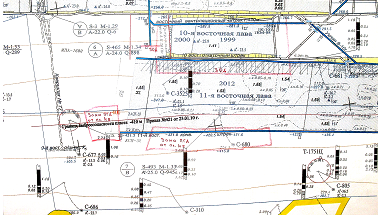
Fig. 1. Lay out of the 11th eastern face of the bank k3 at a map of mine working

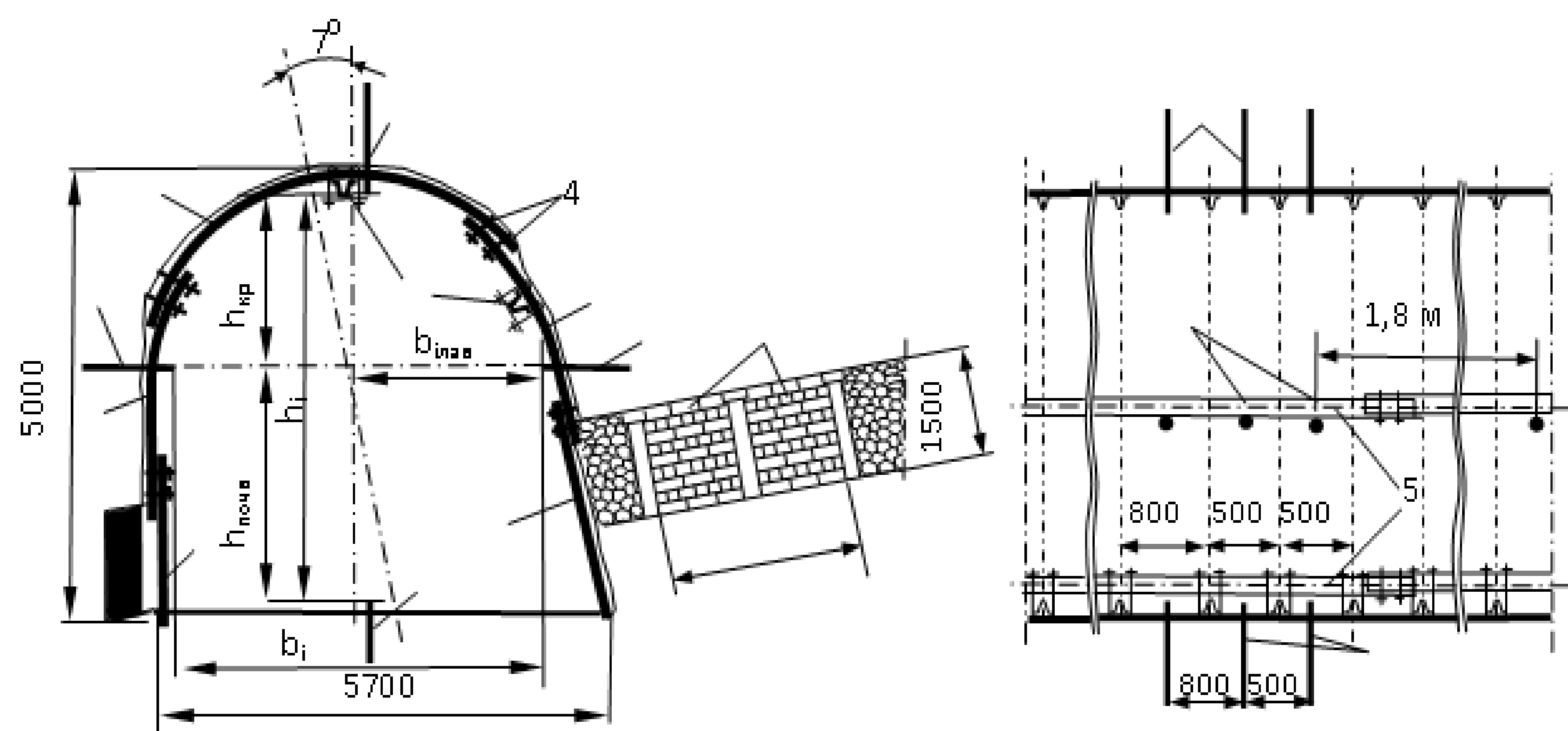
As the mainlining of the belt entry was  used metal ovoid lining KMP-A5KM-12,8  with a density of  main ring installation on the strike of 1.74 g/m. auxiliary measures to protect the belt entry was carried out  enables concrete nonyielding holdout rib from rock halfblock with a rib width on the dip of  2.0 m[2] (Fig. 2).

The interface circuit of haulage roadway with the 11th eastern face of the bank k3

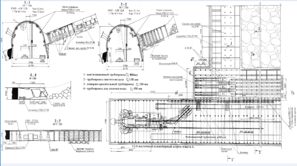
Fig. 2. The interface circuit of haulage roadway with the 11th eastern face of the bank k3

For observing  pushing of partition rock at the workings contour in the belt entry 11th eastern face of the bank k3 in the control and technical experimental area with length of 40 m, were constructed contour observation stations [3](Fig. 4).

Control plot the traditional method of fixing production arched roof supports compliant KMP-A5 with an asymmetrical arrangement of  locks of the main lining and installation before and after the face individual metal racks lining amplification of two segments of a special profile SVP-27 were used[4].

On the first experimental plot of  belt entry of 11th eastern face of the bank k3 kits of  arch collapsible timbering KMP-A5 were linked by single length braced lining gain(LBLG)[5], which was placed in drifting face with a lag up to 4 m.

Displacement of the roof rocks and soil in the development

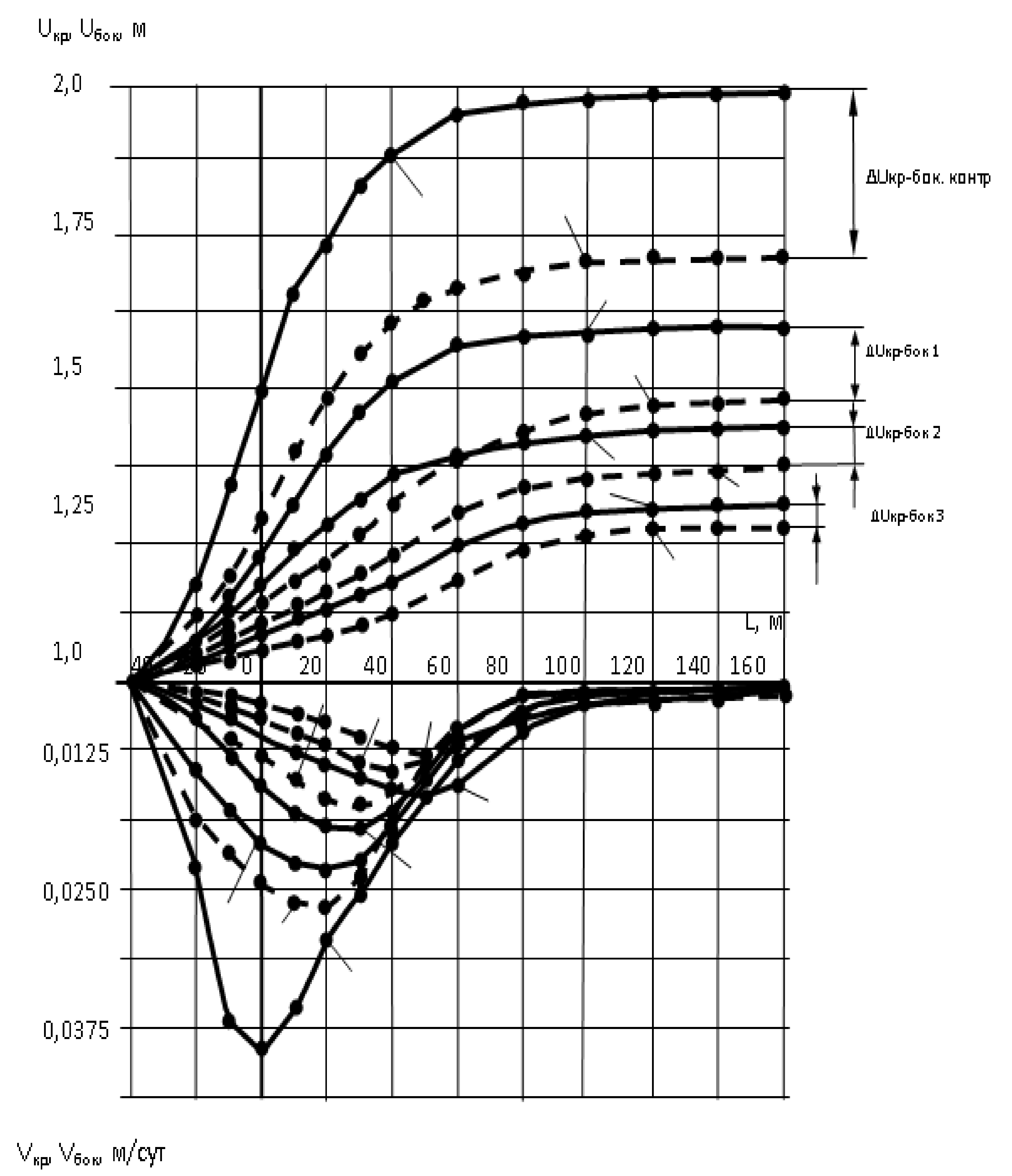
Fig. 3 . Displacement of the roof rocks and soil in the development

(animation: size — 52 KB; 250x170; number of frames — 4; cycles of repetition — 5; the delay between shots — 1)

Longitudinal girder is made of special shape SVP-27 was suspended in the center of workings of each frame to the roof bar secured with two long metal hooks with a cross-sectional diameter of 0.024 m, a metal bracket and two nuts[6] (Fig. 4). Cuts beam length of 4.0 m were joined together by overlapping 0.2 m two clamps M24.

In the second experimental plot of  belt entry kits  of ovoid (tent) supple lining A5KM-KMP-12,8 were linked by single longitudinal beam bolting gain special section of the segments SVP-27, which was placed similarly to the first portion[7].

In the third experimental plot of belt entry kits of ovoid (tent) were reinforced lining double longitudinal beam supports. Vertical arm was mounted similarly to the first and second experimental sites, and an auxiliary girder was suspended to the rack of lining by the side of face at a distance of 0.3 m below the lining  locks, which was due to intencive ettle motion of immediate langing wall under settlement the main roof and gradually set of load bearing strength by the holdout ribs  which are build up on the brow of face.

Fig. 4. Layout contour metering station in the belt entryof the 11th eastern face of the bank k3  in section (a) and plan (b) of workings at the location of the two beams of SVP-27 perimeter ovoid lining: 1 - roof girder; 2, 3 - vertical and inclined racks lining; 4 - locks lining; 5 - longitudinal beam lining gain; 6, 7 - respectively, the upper and lower contour benchmarks; 8 - side benchmarks; 9 - rigid support band of rock on the edge of the lava semiblocks.

Surveillance Scheme displacement of wall rocks

Fig. 4. Surveillance Scheme displacement of wall rocks

Fig. 5 shows plots of the lateral pushings of the rocks wall on the belt entry contour under different modes of it`s supporting.

At thre control plot that are not linked by longitudinal girder support assembly due to their segregated work perceive increased stress earlier and severe deform one by one with the destruction of the lining elements[8].

Application of longitudinal beam lining gain  with asymmetrical arrangement of locks of the main lining and single-longitudinal-beam coupling os sets lining was possible to reduce the magnitude of vertical displacements at 0.77 m or 1.6 times compared to mine one without reinforcing lining (Fig. 4). Using single-and double LBLG with symmetrical locks  arrangement vertical displacements were reduced by 1.1 and 1.37 m or 2.25 and 3.26 times[9]. However he maximum value of the displacement velocity decreases with increasing rigidity of lining gain, and their location shifted towards the  goaf.

 Dependency diagrams of vertical and horizontal displacement

Fig. 5. Dependency diagrams of vertical (1, 2, 3, 4) and horizontal (11, 21, 31, 41) displacement and velocity of displacement of the roof rocks in the belt entry of the distance from the lava: 1 - with traditional technology of workings supporting; 2 - using a single longitudinal beam lining with asymmetrical locks; 3 and 4, respectively, using single and two-beam gain lining with symmetrical locks

Conclusion

Thus, as a result of mine observations revealed that the use of longitudinal girder connection of basic lining sets allows them to usable state as a conjunction with the breakage face and in the zone of influence of goaf. Longitudinal-transverse stability of the main roof support frame is provided by connectionof linings kits of nonyielding longitudinal girder, redistributive increased load between overloaded and underloaded lining kits and removing their turn and skewed length of development.

References

  1. Заславский Ю.З. Исследование проявлений горного давления в капитальных выработках глубоких шахт Донецкого бассейна. М.: Недра, 1966. – 180 с.
  2. Литвинский Г.Г., Гайко Г.И., Кулдыркаев М.И. Стальные рамные крепи горных выработок. – К.: Техника, 1999. – 216 с.
  3. Бабиюк Г.В. Управление надежностью горных выработок: монография / Г.В. Бабиюк. – Донецк: «Світ книги», 2012. – 420 с.
  4. Черняк И.Л., Ярунин С.А. Управление состоянием массива горных пород. М.: Недра, 1995. – 395 с.
  5. О. Якоби. Практика управления горным давлением. М.: Недра, 1987. – 566 с.
  6. Соловьёв Г.И. Определение параметров силового взаимодействия арочной крепи и жесткой продольной балки // Вісті Донецького гірничого інституту, № 2, 2005 р., C. 90-100.
  7. Соловьёв Г.И. О результатах опытно-промышленной проверки эффективности способа продольно-жесткого усиления арочной крепи выемочных выработок глубоких шахт // Геотехнічна механіка: Міжвід. збірн. наук. праць / ІГТМ ім. М.С. Полякова НАН України. - Дніпропетровськ. 2005. – Вип.61. С. 274-284.
  8. Соловьёв Г.И. Особенности физической модели самоорганизации боковых пород на контуре выемочной выработки при продольно-жестком усилении арочной крепи // Науковий вісник НГУ, Дніпропетровськ. 2006, № 1. С. 11-18.
  9. Соловьёв Г.И. О влиянии продольно-балочной связи рам податливой крепи по длине выемочной выработки на работу замковых соединений / Соловьёв Г.И., Голембиевский П.П., Мороз О.К., Кавера А.Л., Шелепа А.А. // Научные материалы международной конференции “ХI Szkola geomechaniki”. Гливице - Устронь. 15-18 октября 2013г. С. 1-8.