
Abstract
Contents
- Introduction
- 1. Objectives and tasks of the study
- 2. Key questions that need to be resolved in this work
- 3. The structure of the stand for Research
- 4. Real-time operating systems
- 5. Principle Implementation of software control in real TIME
- Output
- List of sources
Introduction
Development and implementation of new algorithms identify, control and surveillance various electromechanical systems are inextricably linked to the stage of full-scale tests, working off of individual components and the whole system, verification and correction of the basic ideas and models that formed the basis of theoretical research. In the synthesis of control systems for complex electromechanical systems multimass with elastic and non-linear elements necessary mathematical models adequately real system. The reliability of the results obtained during the synthesis of control systems for complex electromechanical multimass Objects can be scanned only when dealing with a real object. One approach to solving this problem is the use of stands that mimic the structure of a control object. At the same time, the original debugging controls and comparing their performance work in conditions close to real, is performed at such a stand, containing all the necessary elements. Research stands for debugging software management systems transducers allowing for the kinematic relations between the drive motor and the driven machine are produced by many electrical companies. However, the cost of such stands is many times the initial cost of production of converters and motors.
1. Objectives and tasks of the study
The aim of this work is to develop mathematical models and methods of synthesis of two-mass regulator Stand electromechanical system, and a study of dynamic characteristics of the synthesized control system stand two-mass electromechanical system.
2.Key questions that need to be resolved in this work:
- Analysis of existing solutions in the field of control systems and equipment converter
- Demonstration of the possible methods of changing the structure of the system and control algorithms complete electric
- Develop a system of automatic control of the electric drive in real time with the use of digital systems
- Modeling of processes in the system established by regulation
3.The structure of the stand for Research
The test is designed for complete electric vector control synchronous motor with permanent magnets (PMSM). Schematic representation of the laboratory complex is shown in Fig. 1.
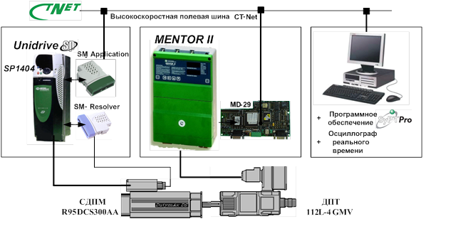
Fig. 1 - Laboratory for the study of complex vector control system PSDM
It consists of two electric cars: SDP Dutymax DS type R95DCS300AAA and DC motor (DPT) independent excitation 112L-4MGV, mounted on the same shaft and rigidly connected to each other. DPT is used as a loading machine for the synchronous motor. SDP is used to control the frequency inverter Unidrive SP1404, and to control the DPT - thyristor converter MENTOR II. An integral part of the transducers are embedded controllers, which are designed to implement basic control algorithms provided by the developers. The frequency converter is equipped with well coprocessor module SM-Application, and thyristor converter - module MD29. Both of these additional modules designed to implement user applications. SM-Application module is based on high-performance specialized processor, equipped with a Flash-memory capacity of 384kb, 80Kb RAM capacity. Module MD29, implemented on a 32-bit RISC-processor INTEL 960; It has 96 Kbytes of flash memory and 8 Kbytes of RAM. In the case of a synchronous machine installed position transmitter resolver. Contact position sensor with a frequency converter via the optional module SM-Resolver. With Hi-Speed CT-Net enables communication between the drive and the computer is also included in the stand and intended for programming of additional modules in the medium SyPT-Pro and maintenance of the virtual oscilloscope ST-Scope in real time [1].
4. Real-time operating systems
Control of electromechanical systems is significantly different from the usual data on the computer. This processing follows the events in the object of control. Digital control system must be fast enough to respond to external events and are constantly processing the input data stream, often without being able to change the speed of their arrival. The same time the system should provide and perform the other, the auxiliary functions – information exchange, processing, preservation and archiving of data, its display, an appropriate response to certain signals, etc. For real-time a mode of computing devices, using special programming techniques because of features inherent in this mode. These features include the fact that real-time system contains not one but several programs, each of which is responsible for solving a particular task, and the relationship between these programs can be very difficult. In addition, the order of the commands of the real time program can not be determined in advance, since it depends on external events and can be changed by interrupts. Therefore, the time required to compute each cycle of operation may vary considerably [3].
The basic requirements for real-time are as follows:
- high priority should always be performed first;
- inversion of priorities should be excluded;
- processes and threads, the execution time which can not be planned, will never be fully occupy the system resources.
To provide real-time operating systems can be implemented the following requirements [4, 5]:
- support for dynamic priorities (which can be changed during the task execution) in a preemptive multitasking kernel (for both processes, as well as for flows);
- the possibility of priority inheritance;
- the possibility of displacement of the core tasks of the operating system;
- Interrupt latency is bounded by (the time during which interrupt is allowed – is the processing time of a critical section of code);
- implementation of operating system services with a priority that is assigned to a customer service.
The most common in the programmable logic controllers and computers for solving problems of automation are operating systems Windows CE, QNX and ОS-9.
5. The principle of implementation of real-time program control
Consider the implementation of
the principle of program control in real-time coprocessor module SM-Application,
which is used to control the frequency converter (Control
Techniques). User application
consists of separate sections (tasks) that are executed in strict
sequence. These sections are (in order of priority): Initial
,
Event
,
Pos
,
Clock
and Background
. When power is applied first to the statements recorded in the section
Initial
,
which are given values of constants and initial values of the
signal control system, and is defined by its configuration. After that,
begin to run real-time tasks of section Pos
(there may be several such Pos0
and Pos1
)
and Clock
.
Instructions are placed in these sections, cyclically repeated at fixed
intervals of time (discrete periods). The period for the discrete task Clock
(T∂1)
can take integer values from 1 to 200 ms, and for tasks Pos0
and Pos1
(T∂2)
– strictly fixed values: 250 ms, 500 ms, 1 ms, 2 ms, 4 ms
and 8 ms.
Regulations sections Event
have the highest priority, so their task contain very small number of
instructions. They interrupt the operation of section Pos
and Clock
,
and only at the end of their performance management program continues
the interrupted instruction sections Pos
and Clock
.
Thus, in the sections Event
advisable to put the algorithms of certain events, such as emergency
situations.
Background
– is a background task. It runs only in the pauses between
the instructions of the other sections. This task is organized in the
form of an infinite loop. If it is completed, it will no longer run.
In figure 2 introduced the concept of mutual termination of tasks [6].

Figure 2 – Time diagram of the implementation specific instructions
(animation: 7 frames, 7 cycles, 20 kilobytes)
Conclusions
In writing this essay master's work is not yet complete. Final completion: December 2015. The full text of work and materials on the topic can be obtained from the author or his manager after that date. It will be held a series of experiments, research and refinement of the available results.
list sources
- Расширенное руководство пользователя Unidrive SP. Редакция 7. Универсальный привод переменного тока для асинхронных двигателей и сервомоторов. – 2004.–381 с.
- Олссон Г., Пиани Д. Цифровые системы автоматизации и управления – СПб.: Невский диалект, 2001. – 557с.
- Ишматов З.Ш. Микропроцессорное управление электроприводами и технологическими объектами. Полиномиальные методы: монография / З.Ш. Ишматов. Екатеринбург: УГТУ-УПИ, 2007. – 278с.
- Денисенко В.В. Компьютерное управление технологическим процессом, экспериментом, оборудованием. – М.: Горячая линия – Телеком, 2009. – 608с.
- Сорокин С. Системы реального времени // Современные технологии автоматизации. №2, 1997, с. 22 – 29.
- Руководство пользователя SM-Applications. Дополнительный модуль для Unidrive SP. Редакция 4. – 2004. – 113 с.
- Толочко
О.И. К
вопросу об изменении типовых структур цифровых систем управления
комплектными электроприводами / О.И. Толочко, П.И. Розкаряка, Н.М.
Горобец // // Наукові праці ДонНТУ. Серія:
Електротехніка і енергетика
. – Вип. 10 (180). – Донецьк: ДонНТУ, 2011. – C.188-193. - Толочко О.И., Коцегуб П.Х., Розкаряка П.И. Синтез задатчика положения с ограничением рывка при учете статического момента // Вісник Кременчуцького державного політехнічного університету: Наукові праці КДПУ. – Кременчук: КДПУ. – 2008. – №3 (50). – Ч.1. – С. 58-63.