
Abstract
Contents
- Introduction
- 1. Theme urgency
- 2. Goal and tasks of the research
- 3. Analysis of sources
- 4. Research results
- Conclusion
- References
Introduction
Over the past 200 years it has been actively developing science and technology. At the same processes are improved rapidly for the better. Mankind has always aspired to something better. After what happened yesterday – is not enough for today...
More recently, in 1887, Galileo Ferraris and scientists Nikola Tesla made a huge contribution to the creation of asynchronous motors. After that, scientists around the world began to pay attention to the improvement of induction machines. These inventions laid a strong foundation for mass industrial use of electric machines.
1. Theme urgency
Because of the asynchronous motor (AM), virtually all processes in enterprises are automated and do not require for such a large number of people as before, the rate of production of a product many times growing. Using AM allows many times to reduce the company's budget, while getting high profits.
Recently, much attention is paid to the possibility of increasing the power is an AC electric motor, which leads to increased losses in AM [1].
Therefore master's work is devoted to actual scientific problem of development of possible methods of increasing capacity in asynchronous motor with minimal loss of energy in the AM.
2. Goal and tasks of the research
The aim is to investigate the possibility of increasing the power of the induction motor by adjusting the nominal rate up for a constant magnetic flux.
Main tasks of the research:
- To analyze the impact of the proposed principles regulating the voltage and frequency on the thermal state of AM.
- To analyze the impact of the proposed principles regulating the voltage and frequency on the thermal state of the transistor switches.
- To assess the change in the overall efficiency of the system.
Object of study: asynchronous electric drive
As part of the master's work is to get the actual scientific results in the following areas:
- The proof of the possibility of increasing capacity in asynchronous motor AC by a simultaneous increase in f and U.
- Proof of energy efficiency of the proposed method of increasing power.
For experimental evaluation of the theoretical results and the formation of the foundation of further research, as the practical results of plans to develop high – speed mathematical Simulink – model system in the program Matlab.
3. Analysis of sources
The thesis developed a method of controlling the frequency – controlled electric drive on the basis of the maximum equivalent load (fig. 1a), taking into account the influence of other actuators that are associated with one process.
This method consists in regulating time pause the most critical from the standpoint of overload electric drive by limiting the speed of interconnected drive depending on its thermal condition, which is determined using the thermal model.
In [1] found that the overload capacity of frequency – controlled electric drive is dependent on engine speed. At the same time, this dependence is extreme. Maximum overload capacity is achieved at a speed close to the nominal 0.75 in the case of Self – cooled motor.
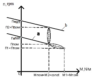
Figure 1 — The mechanical characteristics of asynchronous electric drive:
a) natural (power increase by increasing the load on the engine);
b) artificial (capacity increase by regulating the speed up of the nominal without field weakening)
At the same time, remain unexplored questions power augmentation by controlling the speed up from rated without field weakening (fig. 1b). Primarily, this is due to the engine power, voltage and frequency above the nominal value. This is possible since the frequency converter may increase the frequency and amplitude of the output voltage higher than the nominal, if the [2]:
— Use voltage sourse rectifier (VSR) step – up feature that can increase the voltage in the DC link.
— When using overmodulation in a voltage sourse inverter (VSI).
In the first case, we have the ability to increase voltage in the DC link from 535 V to 600 V (fig. 2a). That is, the frequency converter is underutilized voltage in DC link (about 10%).
Then, by increasing the voltage of the DC, may increase the voltage on the engine, also at 10%, which in turn would lead to increased productivity electric drive that is necessary and possible to use.
In the diagram (fig. 2b), the transition to the regenerative operation (fig. 2a), the dynamical error in Udc regulation, accompanied by an increase of this magnitude. Since the transistor module tightly regulated voltage, in further studies, plans to create a high – speed control system electric drive to reduce the dynamic error in working off a given voltage in DC link. To do this the system must be astatic load or have minimal static load.
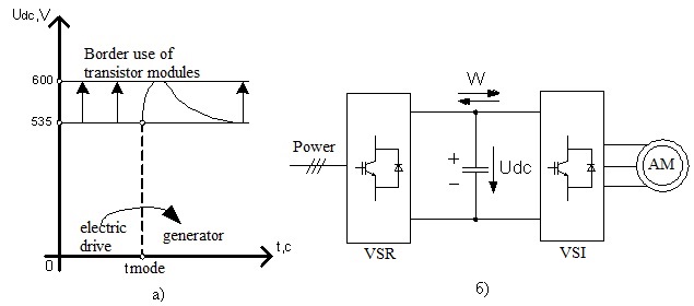
Figure 2 — Voltage as a function of time Udc(t) asynchronous electric drive (a); FC in DC link (b)
4. Research results
In operation, the asynchronous motor is the process of converting electric energy in AC into mechanical energy of rotational motion. This transformation, as well as other electrical machines, due to the loss of energy (fig. 3), so the useful power output of the engine P2 is always less power output P1 on the value of power loss Р:
Figure 3 — Energy diagram of an induction motor
(animation: 5 frames, delay 0.7 s., 3 cycles of repeating, 36 kilobytes)
Consumed active power from the network:
where m – the number of phases, U1 – voltage on the stator winding, I1 – current in the stator winding, cosf1 – motor power factor.
In the thesis [1], the voltage is not regulated, the power increases with increasing load on the engine, wherein the currents in the stator also increase, which in turn leads to a rapid heating of the engine, thus increasing power loss.
While increasing f and U – increased magnetic losses only. However, an increase of 2% (pu) of the total loss has little effect on the thermal state of the engine, and can be fully compensated for self ventilated motor [3]. It is also possible the adjustment of the control law FC – AM, which implies a slight decrease in the magnetic flux in which magnetic losses are permanent. It is possible to use a motor with forced ventilation.
It can be concluded that the real engine efficiency is increased by 0.5 – 1% (big numbers correspond to larger nominal values efficiency AM).
Efficiency AIV and ARV reduced by increasing the switching loss component of semiconductor devices by 10% [6]. The voltage on the switch will not exceed the value of the passport 600V.
The loss of conductivity of semiconductor devices [6], depending on the output current, thus remain unchanged at AIV, while the ARV will increase by 10% by increasing the current in network, the proportional output power AIV. Hence the power ARV is too high, and is selected by the ultimate power of AM.
Since the total loss of AIV and ARV are about 4% [6] of the output power, hence, if the voltage increases by 10% the overall efficiency of the converter is reduced by no more than 0.4%. At the same time the overall efficiency of the frequency converter – induction motor is not reduced.
Conclusions
- The possibility of increasing capacity in asynchronous motor AC by a simultaneous increase in f and U.
- Proof of energy efficiency of the proposed method of increasing power.
- The developed high – speed control system electric drive to reduce the dynamic error in working off a given voltage DC link.
- The modeling process in the drive.
In the process of abstract writing the master's work hasn't been finished yet. Date of finish: December, 2015. The full thesis of master's work and materials according to the theme may be received from the author or his scientific advisor after the pointed date.
References
- Худолий С.С. Повышение эффективности работы частотного ЭП путем управления по максимально нагрузочной способностью: диссертация на получение научной степени кандидата технических наук / C.C. Худолий. – Днепропетровск: НГУ. – 2014. – 177 с.
- Шавьолкін О.О. Перетворювальна техніка: навчальний посібник / О.О. Шавьолкін, О.М. Наливайко; за загальною ред. канд. техн. наук, доц. О.О. Шавьолкіна. – Краматорськ: ДДМА, 2008. – 328с.
- Шрейнер Р.Т. Электромеханические и тепловые режимы асинхронного двигателя в системах частотного управления: Учебное пособие. / Р.Т. Шрейнер, А.В. Костылев. – Екатеринбург: 2008. – 360 с.
- Пивняк Г.Г. Современные частотно – регулируемые асинхронные электроприводы с широтно-импульсной модуляцией: Монография / Г.Г. Пивняк, А.В. Волков – Днепропетровск: НГУ, 2006. – 470 с.
- Шавьолкін О.О. Експериментальне визначення модуляційних втрат енергії в асинхронному двигуні / О.О. Шавьолкін, Д.М. Мірошник, В.В. Божко// Збірник наукових трудів
Гірнича електромеханіка та автоматика
. – Дн-ськ: НГУ. – 2013. – вип. 91 – С. 25 – 29. - Шавёлкин А.А. Расчет потерь мощности в силовых ключах преобразователя частоты с промежуточным импульсным преобразователем напряжения/ А.А. Шавёлкин, Д.Н. Мирошник// Наукові праці ДонНТУ. Серія
Електротехніка та Енергетика
, випуск 98, Донецьк: ДонНТУ, 2005. – С.116 – 120. - Онищенко Г.Б. Автоматизированный электропривод промышленных установок / Г.Б.Онищенко, М.И.Аксенов, В.П.Грехов, М.Н.Зарицкий, А.В.Куприков, А.И.Нитиевская; под. общей редакцией Г.Б.Онищенко. – М.: РАСХН, 2001. – 520 с.