
Content
- Introduction
- 1 Theme urgency
- 2 Goal and tasks of the research
- 3 System design and function of the airlift
- Conclusion
- References
Introduction
Transportation drop liquid and hydraulic mixtures is provided by volumetric and hydrodynamic pumps, the latest of which applies to the airlift.
Airlifts are hydraulic devices with a sufficiently difficult, not fully investigated, taking place predominantly in the riser hydrodynamic processes movements liquid mixtures (often with inclusions of solid particles). Consequently with far from being perfected existing analytical models [2].
1 Theme urgency
Airlift in demand in the mining, energy, steel and other industries. This is due to high reliability and simplicity, hence cheap manufacturing, installation, maintenance and operation, especially during transportation of abrasive hydraulic mixtures [8].
Of the above shows the relevance and importance of the scientific problem, is to further develop the theory of the working process airlifts. This will increase the efficiency of gas-liquid lifts.
2 Goal and tasks of the research
The executed researches will allow determine the area of a rational exploitation of airlifts and optimal mode of work, which are established on the basis of working process regularities gas-liquid lift. It will enable to reduce costs of transportation liquids (hydraulic mixtures) due to the reduction energy consumption.
Research object: the process of transporting slurry with compressed air in a vertical pipe of airlift.
Research subject: parameters of working process the airlift: inning, air consumption, speed, pressure and power of the water-air flow and components.
3 System design and function of the airlift
Work of the airlift begins with putting into operation of the compressor. Compressed air for air supply pipe 1 is served into the mixer 2, where the process of mixing (interaction) of compressed air and liquid. As a result, the liquid moves through the supply pipe 3 out of the tank (sump) and mixed with air in the mixer forming liquid-gas mixture which moves through ascending pipe 4 in the air separator 5. In an air flow separation occurs on the air that comes out into the atmosphere and water.
(Qn – air consumption, Qе – supply of airlift, Δhn – excess of the liquid column during the start, h – dipping the mixer, H – lifting height slurry)
Figure 1 – Launchers regimes of airlift (positions: 1 – air supply pipe; 2 – mixer; 3 – supply pipe; 4 – ascending pipe; 5 – air separator)
(animation: number of shots – 21, the number of repetitions is unlimited, the amount of 109KV)
The basic equation of airlift [3]
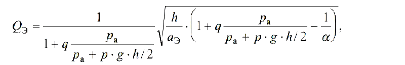
or
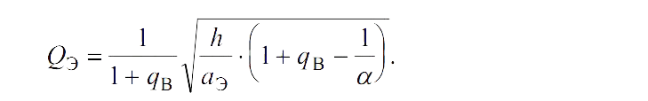
where: aэ – coefficient of resistance the riser pipe of airlift;
h – geometric dipping the mixer;
pа – the atmospheric pressure;
ρ – density of the the environment;
g – acceleration of gravity.
The dependences show that the filing of airlift at constant relative immersed in a large extent depends on the air. The dependence of the supply of airlift from the air flow determines the performance curve of airlift. The most reliably It can be received experimentally. Graphically flow performance for a specific of airlift, and the relative depth of immersion, is a curve, the form of which is shown in figure 2.

Figure 2 – Expenditure Qэ = ƒ(Qв) and energetic ηэ = ƒ(Qв) characteristics of airlift
Energetic characteristic determined by an efficiency of airlift, that is the ratio of useful power to lift slurry supplied to the power of the air flow:
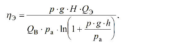
Figure 2 shows the expenditure and energetic characteristics of airlift. Regime of operation in which the efficiency action has the greatest value, is the best and is determined by point A tangent drawn the origin to the flow characteristics of airlift. Working area of airlift is the aggregate his regime, under which the values of efficiency not less than 85% of its maximum value – the zone BC (fig. 2).
Conclusion
The executed researches will allow determine the area of a rational exploitation of airlifts and optimal mode of work, which are established on the basis of working process regularities gas-liquid lift. It will enable to reduce costs of transportation liquids (hydraulic mixtures) due to the reduction energy consumption.
This master's work is not completed yet. Final completion: December 2015. The full text of the work and materials on the topic can be obtained from the author or his head after this date.
References
- Энциклопедия эрлифтов / Ф. А. Папаяни, Л. Н. Козыряцкий, В. С. Пащенко, А. П. Кононенко. – М.: Информсвязьиздат, 1995. – 592 с.
- Кононенко А. П. Рабочий процесс эрлифта и его моделирование. Монография. – Донецк: ДонНТУ, 2010. – 171 с.
- Гідромеханізація: навчальний посібник. М. Г. Бойко, В. М. Моргунов, Л. М. Козиряцький, О. В. Федоров. – Донецьк: ДНВЗДонНТУ, 2011. – 554 с.
- Методические рекомендации по применению средств механизации очистки шахтных водосборных емкостей/ В. Г. Гейер, В. С. Дулин, В. И. Лазаренко, В. М. Яковлев. – Донецк: ДПИ, 1983. – 50 с.
- Кононенко А. П. Энергетическая эффективность эрлифта / А. П. Кононенко // Науковий журнал Вісник Донецького університету. Серія А, Природничі науки. – Донецьк: ДонНУ, 2006. – № 1, Частина 1.
- Средства гидромеханизации : учеб. пособ. / З. Л. Финкельштейн, Л. Н. Козыряцкий. – Алчевск: ДонГТУ, 2013. – 168 с.
- Бойко М. Г., Козиряцький Л. М., Кононенко А. П., Землесосні та ерліфтно – землесосні снаряди: Навч. посібник. – Донецьк: ДонНТУ, 2005. – 296 с.
- Кононенко А. П. Теория и рабочий процесс эрлифтов. Дис. докт. техн. наук. – Харьков: НТУ «ХПИ», 2007. – 565 с.
- Костанда B. C., Логвинов Н. Г., Скорынин Н. И. Определение основных эксплуатационных параметров эрлифта с длинной подающей трубой и несколькими смесителями. – Донецк, 1982. – 12 с.
- Модель рабочего процесса эрлифта в условиях переменных притоков жидкости(гидросмеси). Наукові праці ДНТУ. Серія „Гірничо-електромеханічна“. Випуск 16 (142). – Донецьк: ДВНЗ „ДонНТУ“, 2008. – С. 149–158.
- Кононенко А. П. Структуры двухфазных потоков в подъемных трубах эрлифтов // Вісник Сумського державного університету. Серія – Технічні науки. – Суми: СДУ, 2005. – №12(84). – С. 38–48.
- Гейер В. Г. Новые технологические схемы и средства шахтного водоотлива. – Донецк: ДПИ, 1972. – 35 с.
- Кононенко А. П. Модель рабочего процесса эрлифта с кольцевой структурой водовоздушного потока // Вісник Національного технічного університету „ХПІ“. – Харків: НТУ „ХПІ“, 2006. – №27. – С. 113–121.