
Abstract
Сontents
- Introduction
- 1. Topicality
- 2. The purpose and objectives of the study, expected results
- 3. A review of research and development
- 4. Methods for solving the problem and the current results
- 5. Software development SAU
- Conclusions
- Source List
Introduction
Thermal processes play a significant role in chemical technology. Chemical reactants, as well as their physical transformations, usually accompanied by thermal phenomena. Thermal effects are often the basis of technological processes. Therefore, the question automation exchangers, tube furnaces, evaporators and other objects of Chemical Technology associated with heat transfer to play a significant role.
The main unit fire action refinery ELOU - AVT is the kilns of various types and designs. The most common block furnaces, double-tent-type furnace with radiant walls and vertically - torch type.
1. Relevance of the topic
For commercial oil necessary to carry out the stabilization of oil, that is, to take measures to reduce the ability of the oil to evaporate. The basic process is the stabilization of dehydration and desalting. The bulk of the salt is removed with the water during dewatering, However, to prevent corrosion of equipment, formation of salt deposits and other violations in the process of refining it must be deep desalting in oil supplied fresh water, resulting in a oil emulsion which is then subjected to degradation. The process of destruction oil emulsion is most effective in thermochemical dehydration and desalting, which is based on heating the emulsion and chemical demulsifier impact on it. With increasing temperature decreases the viscosity of emulsions processed fluids constituting emulsion and decreases the surface tension at the interface facilitates separation of water. Heating oil emulsion is often performed in a tube furnace control which is an urgent task.
The tubular furnace is a complex and multi-dimensional multiply connected object Automation. The purpose of regulation is to maintain the kiln product temperature at the outlet with a large number of perturbing effects, many of which are not controlled. Further tube furnace inertia is subject to delay in the main channel regulation . Therefore, the task of choosing the parameter information management, fast reacts to changes to the furnace operation and development of the automatic regulation that would compensate for the main disturbance is actual. Study ways to build SAU outlet temperature tube furnace held for example, heating oil emulsion, which flows through the coil tube furnace and heated by the heat generated by burning fuel gas and air. Of the large number of factors affecting the output temperature of the oil emulsion can isolate a fuel gas supply and oil emulsion. Feeding oil emulsion, as well as the temperature are the main sources of disturbances, and the supply of fuel gas and air - control inputs. The temperature of the air and fuel gas can assumed to be constant.
Management Tasks include: stabilization of the feed Fmat with the influence, to drive the feed pump; stabilizing the temperature of the feedstock at the output of the temperature mode in the oven on the pass To by changing the fuel supply Fr; regulatory process combustion to maximize heat generation by controlling the air supply Fin. Given the large object control advisable inertsialnist introduce preventive control parameter - the flue gas temperature at the inlet TRin.
In Fig. 1 shows the analysis of the heating process in a tubular furnace as a control object, wherein Fmat - material Fr - gas flow, Fin - air flow To - the outlet temperature tube furnace, TRin - inlet temperature tube furnace.
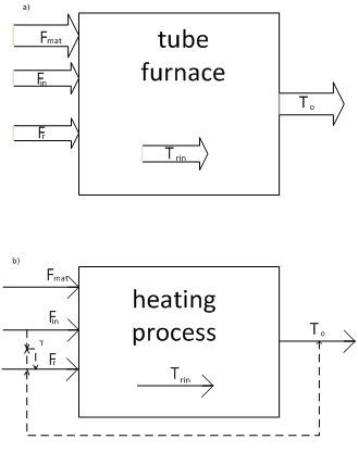
a) the scheme of material flow and information variables,
b) block diagram of ACS.
Figure 1 – Schematic analysis of the heating process in the kiln as a control object
2. The purpose and objectives of the study, deliverables
The purpose of development - to stabilize temperature by keeping the temperature of 70 °C, cost reduction of the fuel gas in the operation of a tube furnace to reduce the cost of the system
The appointment of development - the basic functions performed SAU, functions should be:
- Automatic temperature control oil emulsion and the temperature of the gas above Perevalnoe wall;
- Automatic regulation of gas flow, air and oil emulsion;
- Automatic control of the ratio of gas and air;
- Ensuring interaction with the operating and service personnel.
Research object : block tube furnace type PTB-10E.
3. Overview of Research and Development
The product is fed through a coil tube furnace, heated by the heat generated by burning the fuel gas. Perturbation of the object are:
- flow and temperature of the original product.
- The calorific value of the fuel.
- The amount and temperature of air supplied for combustion.
- The heat loss to the environment.
These disturbances can be compensated for by the temperature of the product in the ACP
the outlet of the furnace, controls the supply of fuel to the furnace. However, the kilns have
delay transmission of heat from the flue gases through the wall of the coil for passing
a coil product. Furthermore, the transition process through the channel fuel consumption
- Product temperature at the exit
lasts several hours. Therefore, when
using single-ACP dynamic error and time control reaches high values.
However, the temperature of the gases over the saddle wall quickly enough It responds to changes to the furnace operation due to a change amount fuel gas supplied for combustion.
Therefore, a significant improvement in the quality control of the product temperature at the outlet of the furnace can be achieved by using a cascade control scheme (Fig. 2), consisting of a control product temperature at the outlet of the furnace (adjustment knob) that affect the job controller gas temperature of the wall of the saddle (stabilizing controller) which controls the supply of fuel to the furnace. Stabilizing regulator starts to compensate arising disturbances affecting the combustion process before they lead to a change in temperature of the product.
When a sudden change in the flow rate of the furnace overload heated and presence of a disturbance on fuel consumption is also used as described above scheme cascade control, stabilizing controller which influences the regulator product flow ratio and fuel. In this case, the ratio controller It controls the supply of fuel to the furnace (Fig. 3).
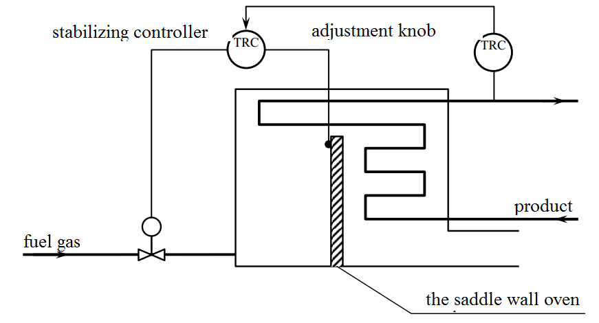
Figure 2 – Driving-related regulatory process kiln
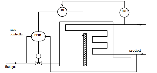
Figure 3 – Cascade control tube furnace with a regulator of the relations fuel gas - the product
When the primary air forced its optimum flow rate at wherein the temperature in the furnace takes a maximum value is maintained with using a ratio regulator fuel gas - air secures the the value of the excess air ratio, determines the intensity of the combustion process.
If the calorific value of the fuel changes significantly, then ratio controller correction signal is sent from the controller stabilization the oxygen content in the flue gases. This ensures complete combustion of fuel and the high quality of regulation. Strong indignation mode kilns by the fuel gas is changing its pressure. This change compensated by the introduction ACP product temperature at the outlet of the furnace additional pressure regulator (Fig. 4), reference to which is supplied from the temperature control in the combustion space.
Such systems provide quality control of fuel gas consumption, because the gas flow is largely dependent on its pressure.
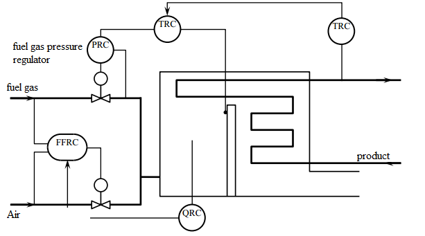
Figure 4 – Functional diagram of the cascade control of the product temperature at the outlet from the regulator ratio fuel gas - air
, and the correction for the oxygen content in the flue gas
When adjusting the ratio of fuel gas - air
is necessary
provide a measure of security, since the lack of air in the furnace can
form an explosive mixture. In this regard, it should provide restriction
fuel consumption, so that the flow will never exceed the maximum permissible value,
corresponding to the current value of the air flow. By reducing the air flow with respect to
certain values must necessarily automatically reduce the supply of fuel to the furnace.
A solution to this problem can be found from the dependence of the temperature in the furnace on the ratio
fuel gas - air
, which is extreme.
Fig. 5 extreme regulator finds the maximum temperature
flue gas over the saddle wall by acting on the regulator
ratio fuel gas - air
, controls the supply of primary air.
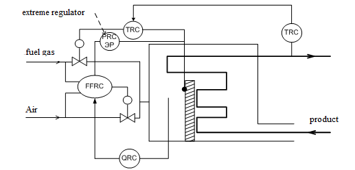
Figure 5 – Driving control of the product temperature in the furnace to extreme control, corrective ratio fuel gas - air
4. Methods for solving the problem and the current results
The analysis of characteristics of the cascade control scheme (Fig.2-5)
the author proposed three-loop cascade scheme of automatic control.
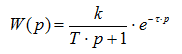
The circuit of this system is presented in the form of a circuit simulation (Fig. 6).
Combined ACS temperature oil emulsion consists of three loops.
The first inner loop - a circuit stabilizing the ratio of costs
fuel gas - air
. It regulates the flow of fuel gas Ftg
in a specific ratio to the air flow Fipov
(The so-called flow ratio controller), so that the restriction on
fuel gas consumption determines the temperature of the wall of the saddle T1:
Ftg=γ(T1)· Fipov
. The second inner loop stabilizes the temperature of the wall of the saddle T1
by changing the flow rate of fuel gas Ftg and changes the job
ratio regulator depending on the temperature of the wall of the saddle T1.
Outer loop - a loop stabilize outlet temperature tube furnace T
by changing the temperature of the wall of the saddle T1.
As a rule, the transfer function of the channel fuel gas consumption - the temperature of the wall of the saddle
,
as well as the channel on the saddle wall temperature - the temperature at the outlet of the furnace
They are of the same type and can be described inertial dynamic links
first order with delay:
As the technology performance requirements CAP outlet temperature of the furnace as follows:
- aperiodic transient overshoot with a valid 0..15%;
- settling time (regulation) is not more than 3e4 c;
- temperature should be between 5 °C to 90 °C.
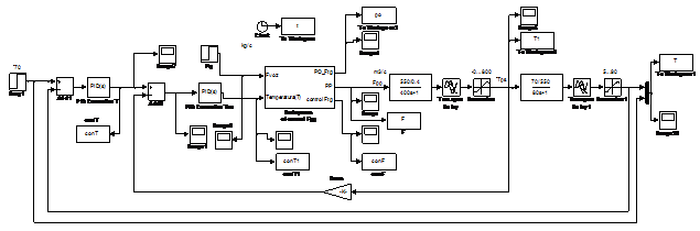
Figure 6 – Scheme three-loop simulation ATS outlet temperature of the tube furnace
The content of the block Subsystem of control Fpp, performing the functions of the ratio regulator is presented (Fig. 7).
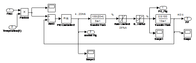
Figure 7 – Power Subsystem of control Fpp
As a method of setting the parameters of regulator method is selected automatically adjust block PID - control simulation package Matlab. The results of the automatic setup provided the specified quality requirements transient temperature oil emulsion (Fig. 8): aperiodic transient overshoot to 7%; control time tp = 2.5e4 with; the range of temperature variation satisfies the routing process of heating oil emulsion: 5 °C and not more than 90 °C.
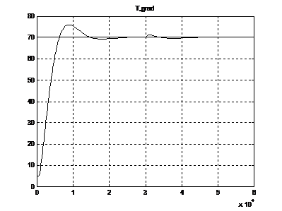
Figure 8 – Schedule transition temperature characteristics of an oil emulsion at the outlet tube furnace
5. Software development SAU
The development of management software kiln quite a challenge, so we restrict the implementation of the algorithm of the main program control tube furnace.
When you run the self-propelled guns necessary to start initialization: start the program management on the PC operator to reset all program variables, check the operation of all the system's sensors, of the system as a whole. Communication with the controller is provided by a computer protocol Profibus. With it, you can monitor and control the process. Next done Running the program on the computer settings and the introduction of a certain temperature and flow rate to start system. Future work program is carried out cyclically. It is conducting a survey of all sensors, processing the values obtained from them, information output to the monitor.
Next, the program will compare the data obtained from the sensors to the inserts, which were introduced earlier, and if any parameter is outside the permissible range, the controller provides control action for the corresponding actuator.
After working the control action over a period of time required for testing, verified its effectiveness - reached parameter is set. If the parameters have reached the desired values, the program returns to the beginning of the cycle.
All of the above can be represented in a block diagram:
Figure 9 – A block diagram of the main program
(animation: 10 frames, interval 700 ms, 232 kilobytes)
Conclusions
- The analysis of existing schemes of cascade automatic temperature control oil emulsion outlet tube furnace.
- A three-loop system for automatic temperature control oil emulsion. The inner loop - Outline of the flow of fuel gas Ftg. Restriction on the fuel gas consumption determines the temperature regulator over the saddle wall T1:. Outer loop - a circuit temperature stabilization outlet tube furnace T.
- We prove the performance of ACS developed a tube furnace by mathematical modeling in Matlab - Simulink. Analysis of the dynamics of ACS kiln shown that the system meets the demands placed upon it and to improve the quality of regulation subject to the restrictions on the performance of the furnace.
- presents developments ACS software and the block - diagram of the main program.
- In the future we plan to test schemes for consideration of possible emergency situations on the formation of explosive mixtures because of lack of air in the furnace will be calculated economic the possibility of introducing the system in operation and developed software ACS.
In writing this essay master's work is not yet complete. Final completion: December 2015. Full text and materials on the topic can be obtained from the author or his manager after that date.
Source List
- Е. Г. Дудникова
Автоматическое управление в химической промышленности: учебник для вузов
. – М: Химия, 1987. - В. А. Голубятников, В. В. Шувалов
Автоматизация технологических процессов в химической промышленности
. – М: Химия, 1985. - Р. Я. Исакович, В. И. Логинов, В. Е Попадько Aвтоматизация производственных процессов нефтяной и газовой промышленности. – М: Недра, 1983.
- Н. В. Жукова, Р. В. Федюн, Н.Н Чернышев Методические указания к выполнению бакалаврской работы (часть II) для студентов, обучающихся по непосредственной подготовкой 6.050201
Системная инженерия
. – Донецк: ДонНТУ, 2013. - Н. В. Кузьменко Учебное пособие для студентов заочной формы обучения по дисциплине
Автоматизация технологических процессов и производств
. – Ангарск, АГТА, 2005. - А. А. Коршах, А. М. Шаммазов Основы нефтегазового дела. – Уфа: ДизайнПолиграфСервис, 2002.
- В. Я. Чаронов Автоматизация работы основного оборудования и проблемы энергосбережения на объектах нефтегазодобычи. – Альтемьевск: Татнефть, 1998.
- Н. В. Кузьменко Автоматизация технологических процессов и производств: Учеб. Пособие. – Ангарск 2005, АГТА. – 78 с.
- Периодическое издание
Нефть, газ и нефтехимия зав рубежом
. – №3, 1987. – 103-104 с., №7, 1987. – 86-92 с. - Периодическое издание
Нефть, газ и нефтехимия зав рубежом
. – №2, 1986. – 114-116 с. - А. А. Кузнецов, С. М. Кагерманов, Е. Н. Судаков Расчеты процессов и аппаратов нефтеперебатывающих промышленности. – М: Химия, 1974.
- Н. Р. Ентус Трубчатые печи. – М: Химия, 1977.
- В. В. Солодовников, А. В. Плотников Основы теории и элементы САР. – М: Машиностроение, 1985.
- А. С. Клюев Автоматическое регулирование. – М.: Энергия, 1973. – 392 с.
- Ю. И. Топчеев Учебное пособие для вузов. Атлас для проектирования систем автоматического регулирования. – М.: Машиностроение, 1989. – 752 с.
- SIMATIC S7-300: Каталог оборудованний. – SIEMENS, 2010г. – 190 с.