
Abstract
Content
- 1. Justification of themes and names, the relevance of the work
- 2. The object and subject of research
- 3. The purpose and objectives of the study
- 4. Analytical Review
- 4.1. Stabilizing support of drilling rig UBM 130
- 4.2. Stabilizing support of drilling rig UBM 130/25
- 5. Stabilizing support of drilling rig UBM-2М
- Findings
- List of sources
1. Justification of themes and names, the relevance of the work
Mineral resources development offshore is inextricably linked with the need to drill a large number of structural and mapping and exploratory wells for solid minerals and geotechnical boreholes for the design and construction of various types of facilities on the sea. Typically, such a well conducted study in the upper layer of the bottom sediments to a depth of 3-4 m to 50 m and concentrated in small areas of water areas [1].
The technical basis of sinking wells to a depth of 15 m and more are drilling rigs specialized courts that implement rotary drilling method with single, double and triple core barrel to reach the regulatory safety and core recovery (not less than 80 %). In some cases the selection process for the preparation of rock samples is limited to dents or precast samplers.
stage of the further development of lung hardware drilling wells on the shelf was the installation of UMB-2M, established under the expansion of the park of drilling equipment GGP Prichernomorgeologiya
. At the same time put forward a number of engineering issues associated with increasing levels of mobility, reliability and stabilizing support in terms of limiting the size of the working areas of the deck of the ship and the parameters of lifting equipment, primarily for the lift height of the bulwark and reach Boom beyond the contour of the vessel.
2. The object and subject of research
Object Research – technical equipment and technological schemes multi-raund drilling geotechnical boreholes in the sea areas.
Subject Research – stabilizing supports and methods of optimization of conditions multi-raund drilling wells on the shelf.
3. The purpose and objectives of the study
The aim is to achieve a new level of efficiency of the installation UMB-2M by increasing the stability of the stabilizing support, as well as its improvements, which will increase the ergonomics [2].
Improving support provides a stabilizing solution of problems:
- Analysis of the concepts of stabilizing supports as part of installations of the UMB.
- Justification of parameters and development of the design of the stabilizing support to increase its stability.
- Increase the reliability of entry of the projectile in the rotary funnel by increasing the length and angle of the socket swivel funnel; as well as to simplify the structure when the lock latch and unlocked.
4. Analytical Review
4.1. Stabilizing support of drilling rig UMB 130
This type of stabilizing support has a fairly simple structure shown in Figure 4.1. Consisting of guide posts, moving carriage, rotatable funnel stops and bottom base. This stabilizing support has a number of drawbacks, first of all, it is wrong configured bottom base and the presence of sharp corners is very bad for the operation of the support [3]. The design of this support is not quite finalized that from a technological point of view, does not play a role, but with the economic playing. Can also be attributed to the shortcomings of that bottom base of the support does not understand. But there is a very important advantage of this support, it is inexpensive to manufacture, and it is fairly simple design.
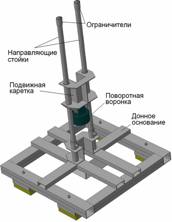
Figure 4.1 – Stabilizing support of drilling rig UMB 130
4.2. Stabilizing support of drilling rig UMB 130/25
In addition to improved design and increased reliability stabilization of GBS at the bottom, in the support, Figure 4.2, provides the ability to disassemble it into separate oversized units. Mortgaged property of the product significantly improved operating conditions, storage and transportation system. This stabilizing Oprah was designed to improve and enhance operational performance. Package includes two independent supports collapsible module as a guide assembly and the bottom base. Structural elements of the guide assembly is movable carriage with rotating funnel and rack rails [4]. The guide posts are used as drill pipe sections with diameters of 50 mm with the supporting cups (diameter segments coring tubes 57 mm) welded to the lower ends of the uprights. The length of the rack is selected from the condition of matching the length of the drill and the working staff of the lift derrick over the bulwarks vessel. One major drawback of this support is to have threaded connections which during operation wearing quickly and require constant maintenance. Also lack of a stabilizing support is that the production of its relatively expensive, and it is impossible not to take into account the fact that the support is made of stainless steel, which indicates its relative softness, but at the same time, stainless steel does not corrode. The advantage is its design as well as the fact that it was proven successful in use.
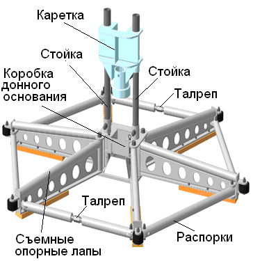
Figure 4.2 – Stabilizing support of drilling rig UMB 130/25
5. Stabilizing support of drilling rig UMB-2М
This stabilizing support is used with the installation UMB-2М, Figure 5.1.
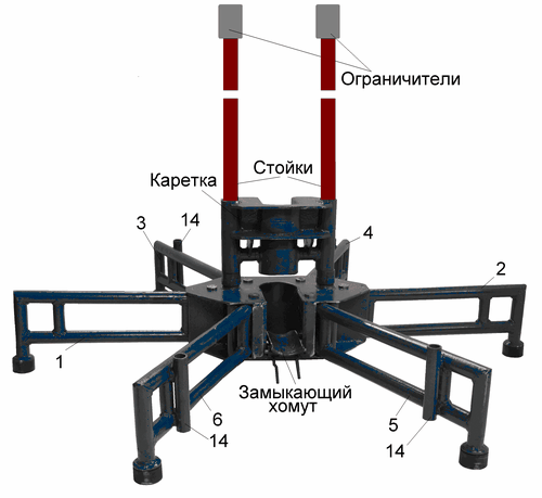
Figure 5.1 – Stabilizing support of drilling rig UMB-2М
Package includes two independent supports collapsible module as a guide assembly and the bottom base. Structural elements of the guide assembly is movable carriage 3 with a rotary hopper 4 and rack rails 2, Figure 5.2. The carriage, Figure 5.3 is designed as a welded body 1 of sheet steel 12-16 mm, equipped with the nozzle 2 (pipe sections KSSK-70). The cylinders are welded to the manifolds, in which the spring-loaded clips 3 are placed which serve to secure the rotary hopper 5. Complete replacement of the carriage is provided with two guide funnel with the drill, respectively, with a diameter of 127-108 mm. When assembling the guide unit 2 in the rack rails are placed mounting bushings 5 ??and collected movable carriage 3. At the top of the racks are fixed removable stops 1. As a guide post used pieces of drill pipe with a diameter of 50 mm bearing cups 6 (segments of core diameter pipes 57 mm) welded to the lower ends of the racks. The length of the rack is selected from the condition of matching the length of the drill and the working staff of the lift derrick over the bulwarks vessel.
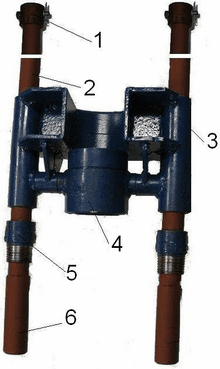
Figure 5.2 – The guide assembly support
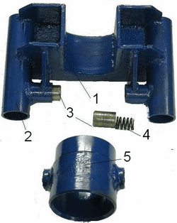
Figure 5.3 – Sliding table stabilizing support
Bottom base includes a rigid bottom compact box 1 set threadless fasteners 2, closing the clamp 3 and six support legs 4 and 13, Figure 5.4. The box body 1 symmetrically placed the nozzle 5 with a threaded mounting bushing guide unit. The end of the box are established Fixed openings for fixing them support legs [5]. In the central part of the box is formed an aperture 6 which is installed on the axle 10 hinged clamp 5. In the closed position the clamp lock is fixed, made in the form of fingers 7 resting on the spring 8, and at the opening of the clamp is recessed radially levers 9. Support bottom base legs are welded frame of the segments of drill pipe diameter of 50 mm. In front paws on the elongated nozzles installed rubber bumpers 11. At the opposite end frames are made of 12 nozzles, which are the mounting element for mounting clutches in the bottom box. The set includes two lateral supports 4 (shortened) and four front (long) legs 13.
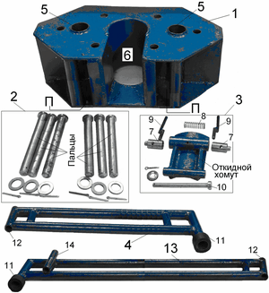
Figure 5.4 – Elements of the bottom base stabilizing support installation UMB-2М
The principal feature of the design of the stabilizing support is its versatility with the ability to use both oneround and multi-raund for drilling wells, thus to work with GBS 108-2M in a movable carriage is replaced funnel included with the installation. It is also possible to use different lengths of the drill with the appropriate placement of constraints on the set of coring.
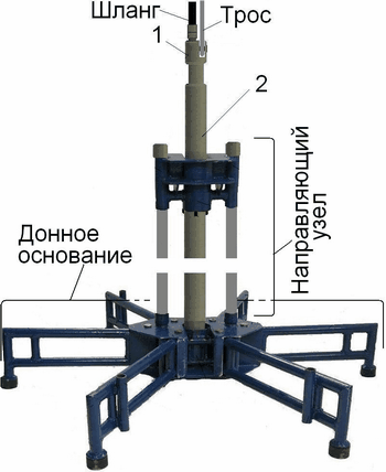
Figure 5.5 – Drilling rig UMB-2M
In the transport position, both modules support versed on several compact units. All of the above facilities (except for guide posts), as well as the traditional accessories (truck adapter, hose connections, control valve and spare parts) are placed in a regular mailbox. In general, the proposed engineering solutions used in the improvement of the stabilizing supports largely complete the task to improve its mobility while reducing the complexity and improving the comfort of working with the installation in a limited size of the working deck areas. The advantages of such a support is the fact that it is inexpensive to manufacture, and has no threaded connections, which eliminates wear at shock loads. Quite a mobile stabilizing support, providing ease of assembly, disassembly, and use. You can not miss the fact that the support is quite easy, on the one hand is good and the other bad influences its stability.
Figure 5.6 – The principle of operation of the apparatus
(Animation: volume – 134 kb.; number of frames – 10; time delay – 0.5 s.; reps – 7)
Findings
This stabilizing support individual as outwardly quite different from previous ones. Its peculiarity is that it is easy to manufacture and relatively inexpensive, which is a very important indicator. Also stabilizes the support of this type is very compact, but its operation has some disadvantages, the sharp edges can lead to work-related injuries. The design of this support also needs to be improved because the lower base is not quite properly positioned. The engineering challenge is to improve one of the stabilizing supports. It is necessary to introduce the amendments to the design, as all of the stabilizing support has its disadvantages, in order to eliminate their need to carefully examine the design and purpose of the stabilizing support.
In writing this essay master’s work is not yet complete. Final completion: December 2015. Full text and materials on the topic can be obtained from the author or his manager after that date.
List of sources
- Калиниченко О. И., Зыбинский П. В., Каракозов А. А. Гидроударные буровые снаряды и установки для бурения скважин на шельфе. - Донецк:
Вебер
(Донецкое отделение), 2007. - 276 с. - Калиниченко О. И., Зыбинский П. В., Каракозов А. А. Разработка погружных гидроударных снарядов для бурения подводных разведочных скважин со специализированных плавсредств. //Сб. научн. трудов. - Вып. 8. - Киев: ИСМ им. В. Н. Бакуля НАН Украины, 2005. - с. 92-95
- Калиниченко О. И., Хохуля А. В., Зыбинский П. В., Каракозов А. А. Установки для бесколонного бурения скважин на морских акваториях. – Донецк: Донбасс, 2013. - 163 с.
- Тарг С. М. Краткий курс теоретической механики. – М.: Высшая школа, 1986. - 410 с.
- Асеев А. Г., Распопов В. М., Хворостовский С. С. Бурение разведочных скважин на шельфе. - М.: Недра, 1988. – 197 с.