Abstract
A circuit of a multi-phase active power filter based on multi-stage inverter architecture was introduced. The paper is focused on building the MATLAB / Simulink model of an AC power supply system including a single-phase active power filter with a two-stage inverter. Each stage of the filter uses the pulsewidth modulation (PWM) method. The results confirmed high efficiency of such a compensating circuit. The presented model will be used for the verification of the bridge-element concept, enabling computer modelling of multi-phase bridge converters, for any number of electrical phases.
1 Introduction
In the near future, multi-phase systems will be considered as design alternatives during the variant design of electric power supply systems. Potential applications of multi-phase systems can be found e.g. among independent power supply systems in aircrafts, in ships, and among those using wind power. Therefore, it is necessary to develop a modelling theory for p-phase independent power supply systems, which is valid for all values of p = 1, 3, 5, 7, … . This would enable computeraided design and power quality analysis of power supply systems consisting of elements with different number of phases in feeding lines.
Results of PSIM analysis of a multi-stage inverter using three-state converters for a singlephase active power filter application were provided in [1]. However, increasing the number of phases in the electric power supply system, p, leads to multiple increase of the number of bridge elements, found in active power filters which are based on multi-stage inverter architecture. For modelling of such systems a bridge-element (B-element) concept was developed and introduced in [2] and [3] . It enables easy building of mathematical models of multi-phase bridge converters, independently of the number of phases, and following integration of them into a p-phase electric power supply system model.
This paper presents a general circuit of a multiphase active power filter based on a multi-stage inverter, with each stage using the pulse-width modulation (PWM) method. Mathematical modelling was performed in MATLAB / Simulink for the example of a single-phase active power filter with a two-stage inverter. It is the ambition to use modelling results for verification of the B-element concept.
2 Multi-phase Active Power Filter
Connection of primary windings of the inverters’ transformers resembles “star connection”, with the following connection to the electric power supply system. Transistors (TR) in the single-phase full-bridge voltage inverters and thyristors (S) in the p-phase thyristor controlled rectifier are assigned their respective numbers.
For simplicity, the function principle of the presented active power filter can be demonstrated for a single-phase connection, Fig.2. Each fullbridge voltage inverter uses PWM being able to produce three levels of voltage.
Each inverter converts some part of the power supplied by the thyristor controlled rectifier. In each stage, PWM is performed by controlling of switching elements. The compensating voltage (AC) of the active power filter is equal to the sum of filtered harmonics, with curtain accuracy. This compensating voltage is in anti-phase with the voltage in the node of connection of the active power filter, and thereby compensating the distortion power.
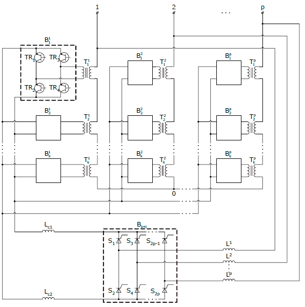
Figue 1 – Circuit of a multi-phase active power filter with multi-stage inverter architecture.
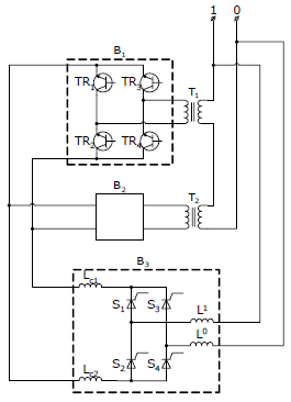
Figue 2 – Single-phase filter with two-stage inverter.
3 Mathematical Modelling Results
In order to demonstrate efficiency of the active power filter, a block-oriented simulation program MATLAB / Simulink was used for modelling the single-phase active power filter being a part of an electric power supply system. The system included a 1 kW synchronous generator and a single-phase rectifier bridge with a 0.75 kW active load.
MATLAB / Simulink graphical representation of the electric power supply system is shown in Fig.3, where L1 = L0 =14mH, C = 500, R = 5, Rload = 484. Fig.4 provides a graphical representation of the filter circuit, whereas the control system is shown in Fig.5. In order to construct the model of the electric power supply system, standard blocks were used (generator, universal bridge), as well as blocks newly created (active filter) based on the standard MATLAB / Simulink elements. The universal bridge block represents the rectifier bridge whose power is defined by its load and is comparable to the power of the synchronous generator.
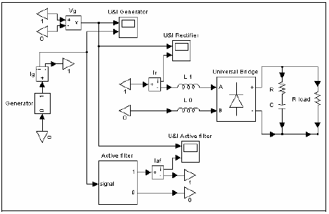
Figue 3 – Graphical image of the electric power supply system.
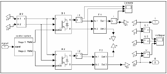
Figue 4 – Graphical image of the active power filter circuit.
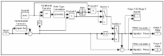
Figue 5 – Graphical image of the control system.
Furthermore, MATLAB / Simulink current and voltage measurement blocks were used for measurement of instantaneous voltages and currents in the circuit. Scope blocks were used to display signals generated during simulation.
Calculation of currents and voltages were performed in time domain, and results were monitored for the time interval between 0.1 s and 0.2 s. The filter started to function at the time t = 0.145 s. The chosen time interval enabled to observe the currents and voltages before and after filtering.
Fig.6(a)-(b) shows compensating currents generated by inverters B1 and B2 in the primary winding of transformers T1 and T2 , respectively. In Fig.6(c), the total compensating current is presented. Fig.7 provides time-domain results for the voltage and current of the synchronous generator. The voltage and current waveforms before and after filtering can be seen.
In Fig.8, current and voltage spectra are presented in order to demonstrate the filter efficiency in the frequency domain. As can be seen in Fig.8, the higher order harmonics almost disappeared after filtering (white bars). The active power filter significantly improved power quality in the electric power supply system.
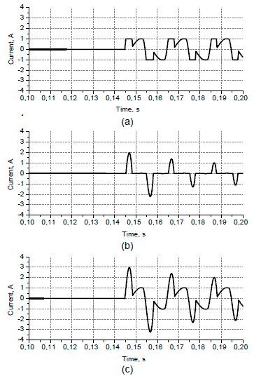
Figue 6 – Compensating current: (a) generated by B1 in the primary winding of T1; (b) generated by B2 in the primary winding of T2; (c) total current, generated by the two-stage inverter.
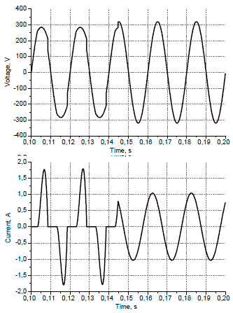
Figue 7 – Voltage and current of the synchronous generator as functions of time.
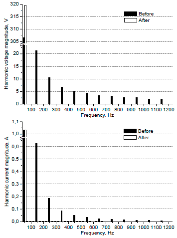
Figue 8 – Voltage and current spectra of the synchronous generator before and after filtering.
4 Conclusion
filter based on a multi-stage inverter with PWM was introduced. Mathematical modelling results obtained for the example of a single-phase active power filter with a two-stage inverter, confirmed high efficiency of the studied compensating circuit. The MATLAB / Simulink model of the AC power supply system including the active power filter will be used in verification of the B-element concept for easy building of mathematical models of multiphase bridge converters, independently of the number of phases.
References:
1. M. Ortuzar, R. Carmi, J. Dixon and L. Moran,
Voltage Source Active Power Filter, Based on
Multi-Stage Converter and Ultracapacitor DCLink,
Proc. of IEEE Industrial Electronics
Conference, IECON'2003, Nov. 2–6, 2003,
Roanoke, Virginia, USA, pp. 2300–2305
2. V.F. Belov, Computer-aided EMC Design for
Autonomous Power Conversion Systems,
Mordovian State University Press, Saransk,
1993 (in Russian).
3. V. Belov, I. Belov, V. Nemoykin, A.
Johansson, P. Leisner, Computer Modelling
and Analysis of EMC in a Multi-phase
Electrical System, Proc. of National
Conference in Computational
Electromagnetics, EMB04, Goteborg, Oct 18–19, 2004, pp. 294–301.