
Abstract
Content
- Introduction
- 1. The urgency of energy conservation
- 2. Energy losses in transient conditions
- 3. Design of the electric motor
- 4. Regulated electric drive as a means of energy saving
- References
Introduction
Currently, the industrial plant should be designed for energy efficiency measures, for each installation. This primarily relates to an electromechanical device with an electric drive, the main element of which is an electric motor. It is known that more than half of all electricity produced in the world is consumed by electric motors in electric drives of working machines, tools, vehicles. Therefore, energy saving measures in electric drives are most relevant.
1. The urgency of energy conservation
The urgency of energy conservation and energy efficiency is so evident in recent years that this issue is being discussed both at all levels of government, and in many enterprises. For most businesses, the question of energy efficiency, especially in the context of continuous growth in the value of energy becomes not only a matter of competitive advantage, but also often a matter of survival of the enterprise. A large part of the enterprise energy costs accounted for electric drive, so most enterprises began to reflect on the implementation of energy-saving technologies.
Energy saving tasks require optimal solutions not only in the operation of electric motors, but also in their design. During operation, considerable energy losses occur in the engine transient conditions and especially when starting.
2. Energy losses in transient conditions
Energy losses in transient conditions can be significantly reduced by use of motors with smaller values of the moments of inertia of the rotor, which is achieved by reducing the diameter of the rotor while increasing its length, since the engine power must thus remain unchanged. For example, as done in engines crane and metallurgical series, designed to work in intermittent mode, a large number of starts per hour [4].
An effective means of reducing losses in the start-up of engines is start by gradually increasing the voltage applied to the stator winding. The energy consumed during engine braking, is equal to the kinetic energy stored in the moving parts of the actuator when starting. Energy-saving effect when braking depends on the braking process. The greatest energy-saving effect occurs when generating regenerative braking to return energy to the network. With dynamic braking the engine is disconnected from the network, the stored energy is dissipated in the motor and return power to the grid is not happening.
The largest energy losses occur during braking by the opposite connection, when power consumption is equal to three times the value of the energy dissipated in the motor during dynamic braking. At steady state operation of the engine with a rated load energy losses are determined by the nominal value of efficiency. But if the actuator operates with a variable load, the motor slowdown periods load efficiency decreases, which leads to higher losses. An effective energy saving means in this case is the voltage reduction, supplied to the engine during periods of his work with underload. This method is possible to implement energy saving operation in the engine system controlled inverter in the presence of the feedback current load on it. The current feedback signal converter adjusts a control signal causing a reduction in voltage applied to the motor during periods of load reduction.
If AC induction motor drive is operating at the connection of the stator windings triangle
, the decrease in the supplied voltage to the phase windings can be easily
realized by switching the connection of the windings on the star
, since in this case, the phase voltage is reduced to 1.73 times. This method is also expedient
because at such switching is increased motor power factor that also contributes to energy saving.
3. Design of the electric motor
In the design of the actuator it is important the correct choice of engine power. So, the choice of engine inflated nominal power leads to a reduction of its technical and economic parameters (efficiency and power factor), caused by underload motor [5]. This solution when selecting the motor leads to an increase in both capital investments (with increasing power of the engine increases the cost) and operational costs, since a decrease of efficiency and loss of power factor grows, and hence, wasteful power consumption increases. The use of low engine rated power causes them to overload during operation. Consequently, the temperature rising windings overheating, which contributes to reduction of loss and causes engine life. Ultimately there are unforeseen accident and stop the drive, and hence increasing the operating costs. To the greatest extent it relates to a DC motor because of their brush-collector unit, sensitive to overloading.
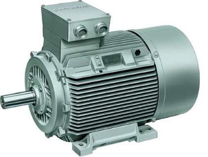
Figure 1 – Motor
Decision contributes to the problem of energy saving application of synchronous motors, established in the mains reactive currents, voltage on the forward–looking phase. As a result, the network is unloaded from a reactive (inductive) component of the current, power factor is increased at this part of the network that leads to a decrease in current in the network and, consequently, to save energy. These objectives pursue inclusion in the network of synchronous compensators. An example of the appropriate use of synchronous motors is the electric compressor systems supplying compressed air company [6]. To do this, start the electric characteristic at low load on the shaft, continuous operation at steady load, lack of braking and reverse. This mode of operation is consistent with the properties of synchronous motors.
Using synchronous motor overexcitation mode, you can achieve significant energy savings across the enterprise. With the same purpose, use the power capacitor banks
(cosine
capacitors). Creating a current in the network, by advancing the phase voltage, these settings partially compensate inductive (lagging phase) currents,
which increases the power factor of the network and, consequently, to save energy. The most effective is the use of capacitor type plants UCM 58 with automatic control
of power factor and with a step change in reactive power in the range from 20 to 603 kvar at voltage 400 V.
Keep in mind that saving is aimed at addressing not only the economic, but also environmental issues associated with electricity production.
4. Regulated electric drive as a means of energy saving
Let us more detail on the regulated electric drive as an energy-saving tool.
The transition from an unregulated to a regulated electric drive is one of the main ways of energy saving in the drive and in the technological field of the electric tools.
Typically, the need to manage the speed or torque of electric machinery production process dictated by the requirements. For example, the feed rate of the cutter determines the purity of the part on a lathe, lowering the speed of the elevator cab is necessary for accurate positioning before stopping, the need for regulation of the moment on the shaft of the winding device is dictated by the terms of the maintenance of constant tension force winding material.
However, there are a number of mechanisms, for which the terms of the speed of technology change is not required for any other use for the control (non-electric) methods of influence on the process parameters. Primarily these include mechanisms for feeding liquids and gases.
Centrifugal mechanisms for feeding of liquids and gases (fans, pumps, blowers, compressors) are the main general industrial machinery, possessing a national scale the highest potential for significant reduction in specific energy consumption. The special position of the centrifugal mechanisms due to their mass, high power, as a rule, long-term operation.
These circumstances determine the significant share of these mechanisms in the energy balance of the country. Total installed capacity of the drive motors of pumps, fans, compressors is about 20% of the capacity of all power plants, with only fans consume about 10% of the total electricity generated in the country.
Operational properties of the centrifugal mechanisms are represented as dependency head H from flow Q, and the power consumption P of Q. In steady state operation the pressure generated by the centrifugal mechanism is balanced by the hydraulic pressure of the wind or the network to which it delivers the liquid or gas.
The static component of the pressure is determined by the pump – the geodetic difference in level of the consumer and the pump; Fan – natural draft; for blowers and compressors – the pressure of compressed gas in the network (tank).
The point of intersection Q – H-characteristics of the pump and the network determines the parameters of N – Hn and of Qn - Regulating flow Q pump is operating at a constant speed, usually carried valve at the outlet and causes a change in the characteristics of the network, resulting in a point of intersection with the pump characteristic corresponds to the supply QA* < 1 [2].
Figure 2 – Q - H – characteristics of the pump unit
(animation: 6 frames, 5 cycles of repetition, 82 kilobytes)
By analogy with electrical circuits regulating valve flow is like the current regulation by increasing the electrical resistance of the circuit. It is obvious that this method of regulation in terms of energy are not effective because it is accompanied by unproductive energy losses in the regulatory elements (resistor, gate). Loss of valve characterized by the shaded area in Fig. 2.
Like as in the circuit, the regulation of souece energy is more economicaly then the consumer regulation. In electrical circuits wherein the load current is reduced by reducing the supply voltage. The hydraulic and aerodynamic networks similar effect is obtained by reducing the pressure created by a mechanism that is implemented decrease in its rotor speed.
If you change the speed of the performance of the centrifugal mechanisms are modified in accordance with the similarity laws, which have the form [1]:
| Q* = ω* , H* = ω*² , P* = ω*³ . (1) |
Impeller speed at which it will pass through the characteristic point A:
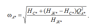 (2) (2) |
The expression for the power consumption of the pump at the speed regulation is as follows:
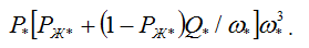 (3) (3) |
The quadratic dependence of the moment of the speed characteristic mainly for the fans, as the static pressure component is determined by natural draft, substantially less NX. In the technical literature, sometimes use approximate dependence on the speed torque that takes into account this property a centrifugal mechanism:
| M* = w*n, (4) |
where n = 2 when NC = 0 and nHC> 0. Calculations and experiments show that n = 2 – 5, with its large characteristic values for compressors working on the network with significant backpressure.
Analysis of the operating modes of the pump at a constant and controlled rate shows that the excess power consumption at ω = const is very significant. For example, the following shows the results of calculating the pump operating mode with parameters HX* = 1.2; РХ*= 0.3 on the network at different backpressure HC [3].
| Q* | 1 | 0.8 | 0.6 | 0.4 | 0.2 |
|---|---|---|---|---|---|
| ω* | 1 | 0.89 | 0.79 | 0.715 | 0.66 |
| P*(ω=const) | 1 | 0.86 | 0.72 | 0.58 | 0.44 |
| P′*(ω=var) | 1 | 0.66 | 0.41 | 0.25 | 0.15 |
| P′Δ*=P*–P′* | 0 | 0.2 | 0.31 | 0.33 | 0.29 |
| P′Δ*/P* | 0 | 0.23 | 0.43 | 0.57 | 0.66 |
| HC* = 0.5 |
| Q* | 1 | 0.8 | 0.6 | 0.4 | 0.2 |
|---|---|---|---|---|---|
| ω* | 1 | 0.94 | 0.89 | 0.85 | 0.825 |
| P*(ω=const) | 1 | 0.86 | 0.72 | 0.58 | 0.44 |
| P′*(ω=var) | 1 | 0.74 | 0.54 | 0.39 | 0.26 |
| P′Δ*=P*–P′* | 0 | 0.12 | 0.18 | 0.19 | 0.18 |
| P′Δ*/P* | 0 | 0.14 | 0.25 | 0.33 | 0.41 |
| HC* = 0.8 |
These data show that the adjustment drive can significantly reduce the electric power consumption: up to 66% in the first and 41% in the second case. In practice, this effect may be even higher, since for various reasons (lack or failure of valves, maintenance) valves regulation does not apply, which leads not only to an increase in energy consumption, but also to excessive head and flow in the hydraulic network.
Above discussed energy issues working singly centrifugal machines on the network with constant parameters. In practice, it meets the parallel operation of centrifugal machines, and the network is often the variables. For example, the aerodynamic drag of the mine network varies with the length of the faces, the drag of water supply is determined by the regime of water consumption, which varies throughout the day [7].
In parallel operation of centrifugal mechanisms there are two possibilities:
- simultaneously and synchronously controls the speed of all devices;
- controls the speed of a mechanism or machine parts.
If network parameters are constant, then in the first case, all mechanisms can be considered as one equivalent for which are valid in all the relations. In the second case, the pressure mechanisms irregular portion provided on the adjustable part of the same effect as backpressure, and it is very important, therefore, power consumption savings are less than 10–15% of the rated power of the machine.
Variable network settings greatly complicate the analysis of collaborative centrifugal machines on the network. Energy efficiency of controlled electric in this case can be defined as a region whose boundaries correspond to the limits of network parameters and the centrifugal mechanism speed.
Remarks
At the time of writing this essay master's work is not yet complete. Estimated completion date: May 2017 The full text of work and materials on the topic can be obtained from the author or his manager after that date.
References
- Energy-saving asynchronous electric drive // IJ Braslavsky, Z.Sh. Ishmatov, VN Polyakov: Proc. allowance for students. Executive. Proc. institutions. - M .: Publishing Center "Academy", 2004. - 256 p.
- Electric drive and automation of plants as a means of energy conservation / IA Auerbach, EI Baratz, IJ Braslavsky, Z.Sh. Ishmatov. - Ekaterinburg: Sverdlovgosenergonadzor, 2002. - 28 p.
- Variable frequency asynchronous electric drive as a means of saving / IA Auerbach, EI Baratz, IJ Braslavsky, Z.Sh. // Energy Ishmatov region. - Ekaterinburg, 2002. - №2 (45). - S. 34 - 35.
- Adjustable electric drives // Firago B. I., L. B. Pawlaczyk - Minsk: Theperspective, 2006.-363p.
- Kopylov I. P. electrical machines. — M.: Energy, 1980. 495p.
- Design of induction motors// V. I. Sechin, Reasonable E. V. - Khabarovsk: Publishing house dvgups - 133p.
- Leznov B. S. energy Saving and variable speed drive in pumping units. M.: IR "Yagorba-Bioinformatic, 1998.