
Abstract
Content
- Introduction
- 1 Relevance of the topic
- 2 The purpose and objectives of the study
- 3 Calculation of the start of the induction motor from the generator of comparable capacity
- 4 The implementation of an autonomous system in the Simulink environment schemes
- Conclusion
- References
Introduction
The use of natural renewable energy resources for the production of heat and electricity is an objective necessity of modern energy.
Inexhaustibility and environmental friendliness of renewable energy sources (RES) on the background of the rapid reduction of fossil fuel reserves,
all the more acute the problems arising for the Earth's climate change and air pollution, make them the most attractive of all existing forms of energy.
In terms of the range of facilities all electrical, drive motor which serves as a wind or water flow, can be divided into electrical systems for large
and small
energy. According to currently accepted classification to facilities class micro
refers to the power plant installed capacity of 100 kW.
In most cases, they are designed to work in an autonomous power supply system on a stand-alone consumer. Larger power plants, tend to work on the electrical network.
This type of power received preferential distribution in the economically developed countries of Europe. The relatively small area, high population density and
infrastructure make the electrical class is economically more attractive. Operational mode of the powerful wind and hydroelectric power plants close to the optimum:
the whole is removed from the primary motor wind or water flow is converted into electrical energy and is transmitted to the electric grid.
To increase the efficiency of these electrical installations is only possible by increasing the efficiency of converting primary energy and reduce the cost of their
construction [1, 2].
1 Relevance of the topic
Without denying the prospect of network power, note the direction of the current use of renewable energy in decentralized power supply systems. Low population density and poor development of transport, energy, industrial and others. Infrastructure in most parts of the country, obviously, determine the relevance and competitiveness of renewable energy in decentralized areas. The main problem of electrical installations using renewable energy sources, while working as part of an autonomous power supply system is considerable variability in time as the energy of the primary energy source, and schedule load energy consumer. And to agree among themselves the inevitable fluctuations of the input and output of energy for obvious reasons it is not possible. Therefore, in most cases, as part of stand-alone power plants that use natural renewable energy, provided the use of a buffer energy storage device (usually battery) and a backup power source (usually a diesel power station). In this regard, specific investment in the power plant operating in stand-alone network, are significantly higher than capital expenditure on power plants operating in parallel with the electric grid. However, while there are significant reserves of increase of efficiency of electrical installations using renewable energy sources in the autonomous power supply systems, not only through the improvement and development of new technical solutions station equipment, but also by providing the most efficient mode of operation [3].
Figure 1 – Circuit with various temperature conditions
Animation: 6 frames, 10 cycles of repetition, 82 kilobytes
2 The purpose and objectives of the study
The purpose and objectives of the research: to calculate the starting process of the induction motor from a synchronous generator power comparable to the autonomous system of several megawatts.
The object of study: the transients at the start of the motor load in the autonomous power supply system in various operating modes.
Subject of research: the parameters defining the nature of the process starter motor load in the autonomous power supply system in various operating modes.
3 Calculation of the start of the induction motor from the generator of comparable capacity
Calculation of starting process of the induction motor from a synchronous generator power comparable to stand-alone power system to produce enough hard several megawatts, and even more so taking into account all relevant factors. The allowable capacity of the engine on the starting conditions can be determined in several ways, but with great accuracy to calculate the variation of the main regime parameters during start-up will not work. In order to simplify the following assumptions, based on the test results of the calculation methodology introduced: not included subtransient process, since it only lasts 2-3 period, ie much less than the entire start-up; turbine generator rotor speed is considered to be constant (in fact, it varies, but within the deadband of turbine control, ie only 3-4%).
In transient analysis of synchronous generators also takes into account the following assumptions: the absence of active resistance elements of the system; the absence of saturation magnetic generator system. The main quantity that determines the character of start-up process and the change of other parameters is the voltage of the generator stator. To define it, we can write the differential equation of the field winding of the generator circuit in the system of relative units in the form of:

where Eqe – emf due to constrained excitation current: the automatic control of excitation, it is variable.
We find the emf synchronous generator based on the assumptions:

On the other hand,

The resistance of the external circuit

where xн – resistance generator preload xк – resistance started-up motor.
Numerous experiments have shown that the generator voltage due to ARV speed is reduced to the nominal long before the moment of a sharp increase in resistance of the motor started-up from him. Therefore, when calculating the generator voltage change can be taken constant resistance started-up motor and equal in relative terms given to the nominal parameters of the generator:

This assumption greatly simplifies the calculations and, more importantly, allows you to find an analytic expression for the change in the stator voltage of the generator at the start of his induction motor.
Substituting (3) into (2), we obtain:

Similarly, for the transition emf generator write:

where

Substituting in (1) in place Eq and Eq' expression (6) and (7) and performing a series of transformations, we obtain the final form of the differential equation:

In this equation taken:


The dependence of the excitation voltage rise when a force on an electrical machine such as a self-pathogen replace an exponential function with a time constant Te

where t1 – delay duration of ARV, indirectly, taking into account the period of time during which the transition process proceeds in the exciter.
Values Te and t1 usually determined from experience. For domestic turbine generators and excitation electric machine for standard devices can take AERs Te = 0,3-0,6 sec., t1 = 0,1-0,5 sec. Recently, for the generators that are used as stand-alone power sources, are commonly used driving system formed on semiconductors. Such systems are almost:. inertia less, ie, when voltage boost to the field winding of the synchronous machine rings increases to limit the jump. To calculate the transients can be taken, that semiconductor excitation system is a special case of the rotary drive, which Te = 0 [4, 5].
Applying Gorev – Park equation for a synchronous machine without damper windings from a purely inductive load, taking into account (11) we obtain the time dependence of the excitation current:

where If0 – excitation current generator until forcing; ΔIfпр=Ifпр - If0 – increment generator excitation current to the ceiling with the boosting of the excitation current.
In view of the assumptions made above in relative units Eqe = Ift. Substituting the expression for the excitation current (12) instead of Eqe in the differential equation (8) and solving the latter, we find an analytical expression that defines the generator voltage change at the start of his induction motor of comparable capacity:

where U0 – the value of the generator voltage when the engine is switched on;
When the rotor speed equal to 70-80% of the nominal, total resistance of the induction motor is comparable with the inductive and has some influence on the start-up process.
According to formula (13) with the help of mathematical MathCAD program had been calculated for the engine capacity of 850 kW and power generator 4 MW. The calculation was obtained a graph similar to that which we have prepared by further work. Figure 1 shows the curve of the analytical calculation based, as determined by the above method.
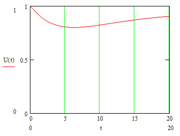
Figure 2 – Starting the engine 850 kW of power generator 4 MW
4 The implementation of an autonomous system in the Simulink environment schemes
Simulink – a graphical simulation environment that enables using the block diagram in the form of directed graphs, build a dynamic model, including discrete, continuous and hybrid, nonlinear and discontinuous systems. Interactive environment the Simulink, allows the use of ready-made library of blocks to model the electric power, mechanical and hydraulic systems, as well as to apply the developed model-based approach in the development of control systems, means of digital communications and real-time devices. Additional expansion packs Simulink can solve the whole range of tasks from concept models to test, test, code generation and hardware implementation. Simulink is integrated with MATLAB environment that will allow use of built-in mathematical algorithms, powerful data processing tools and scientific graphics. Simulink Library Browser (Myramistin view Simulink Library) contains a block library of the most commonly used for modeling systems.
In this library include:
- blocks of continuous and discrete dynamics, such as Integrator (Integrator) and Unit Delay (Delay Link);
- algorithmic blocks, such as Sum (adder), Product (product), Lookup Table (Reference Table);
- building blocks, such as Mux (multiplexer), Switch (switch), Bus Selector (selector tires).
You can perform a simulation of the dynamic properties of the system and see the results as soon as the simulation is started. In order to ensure a predetermined speed and accuracy of simulation, the Simulink ODE solvers provides fixed and variable pitch, a graphical debugger, and time estimation routine performing certain functions of the model.
Solvers – are numerical integration algorithms that compute the system dynamics over a certain period of time, using the information contained in the model. imulink provides solvers to simulate a wide range of system types, including continuous-time systems (analog), discrete-time (digital), hybrid (mixed signal) and systems with different sampling periods of any size. With solvers in Simulink can perform a simulation of stiff systems and systems with discontinuities. You can set the simulation options, including the type and properties of the solver, the start and end of the simulation and perform the download or save simulation data. You can also customize the optimization and diagnostic information. Along with the model, you can save different optional combinations.
Key features of Simulink
- an interactive graphical environment to build a block diagram;
- expandable library of ready-made blocks;
- handy tools for building multi-tiered hierarchical model;
- navigation and settings of complex models – Model Explorer;
- integration tools ready C / C ++, FORTRAN, ADA and MATLAB-algorithms to model the interaction with external programs for modeling;
- modern means of solving differential equations for continuous, discrete, linear and non-linear objects (including hysteresis and breaks);
- simulation of non-stationary systems using solvers with variable and constant pitch or managed by batch from MATLAB simulations;
- handy interactive visualization of output signals, configuration tools and tasks of input actions;
- debugging and analysis models;
- full integration with the MATLAB, including numerical methods, visualization, data analysis and graphical interfaces [6, 7].
Figure 2 shows a diagram of an autonomous system. Generator working on resistive load. This circuit was built in Simulink and used as a basis in the further consideration of the goal.
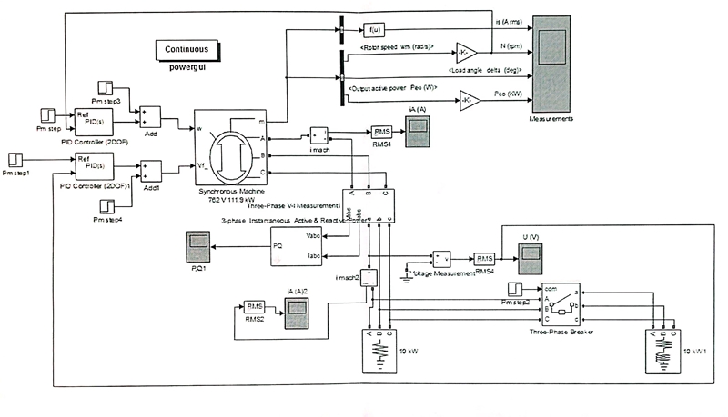
Figure 3 – Scheme of the autonomous system. Generator working on resistive load
Conclusions
The results of the thesis
1 Give the concept of "energy system of limited power", namely: self-contained power supply systems on the basis of the SG, an autonomous power supply systems of thermal and nuclear power, an autonomous PSU, GTU, small hydropower plants.
2 Make the wiring diagram, select the basic equipment, calculate the parameters of equivalent circuits, calculate the steady-state operating conditions and short circuit currents.
3 Investigate the inclusion of motor load at comparable power generator excluding subtransient processes.
4 Simulate an autonomous energy system in Simulink system. Explore regimes modeled system.
*This master's work is not complete yet. The full text and materials can be obtained from the author or his research manager in July 2017.
List of sources
- Popel O. S., Tumanov V. L., Renewable energy sources: state and prospects of development / International Journal of Alternative Energy and Ecology, AEE, № 2 (46) (2007) – 135 p.
- Electronic source: http://lektsii.org.
- Magomedov A. M., Non-traditional renewable energy sources, Jupiter, 1996, 245 p.
- Syromyatnikov I. A., Mode asynchronous and synchronous motors. Gosenergoizdat, 1963.
- Ulyanov S. A., electromagnetic transients in power systems, Energy, 1964, 519 p.
- Electronic source MATLAB and Simulink competence center companies Mathworks: http://matlab.ru.
- Chernih I. V., Simulink: Modeling Tool dinmicheskih systems 2008.