Abstract
Сontent
- Introduction
- 1 Relevance of the topic
- 2 The purpose and objectives of the study, expected results
- 3 Review of research and development
- 3.1 Automatic control system installation of air conditioning
- 3.2 Automation equipment air conditioning systems
- 4 The main results of research and development
- 4.1 Management options
- 4.2 Model of air conditioning system and principle of operation
- 4.3 Simulation control system
- Conclusions
- List of sources
Introduction
In modern conditions of the city’s infrastructure and large industrial air conditioning systems are common, require resource‑technological modes of heating, cooling and humidification to maintain that using modern automation control system.
The indoor air is constantly accomplished the transition from one state to another. To maintain the specified parameters served in the room supply air is fed with parameters different from the settings inside. Serviced room air is characterized by dispersed performance.
The air conditioning system displays the outside air, after measuring its temperature in the pumping compartment determines the recipes work of heating sections, cooling and humidification to achieve the desired temperature and humidity in the room.
1 Relevance of the topic
The main type of air conditioning system control is automatic control, technical subject which is the process of centralization of management of heating, cooling, humidification of the served room, while providing automatic protection from accidents in case of emergency situations.
For air conditioning systems as a control object characteristic of the disturbance at the input (humidity and ambient air temperature) and also important to consider the temperature and humidity of the air after passing through each section. Studies have shown that there is overspending electricity because of the decentralization of the management of such air‑conditioning systems, as well as the efficiency of the whole process is lost changes in air parameters.
High efficiency air conditioning system can only be ensured when the coordinated work of all technological units: heating sections, cooling sections, and the reheat humidifying section section that can be achieved using plant control system. Thus, the automatic control of the heating process of the system, cool air does not perform all the necessary functions to manage and control parameters ACS. Therefore, the development of automatic control system of the heating process, ooling and humidification is relevant.
2 The purpose and objectives of the study, expected results
Purpose – providing continuous conditioning, heating, cooling and humidification, reducing energy costs by developing a system control installation of air conditioning.
The scientific challenge is to develop and study mathematical models of operating modes on the basis of which the air conditioning system justification control parameters, control algorithm and circuit solutions for the control system ACS.
To achieve this goal it is necessary to perform the following research objectives:
- Perform analysis modes of the air conditioning system as the automatic control of objects and formulate the requirements for the control system ACS;
- Create mathematical models of the processes of heating, cooling and humidifying the air in the management of the developed automatic control system ACS;
- To substantiate and develop a control algorithm and circuit solutions for the installation of the control system.
3 Review of research and development
3.1 Automatic control system installation of air conditioning
Issues of creation of automatic control systems, heating processes, cooling and humidification are devoted to many works, for example, Р. Дорф, Р. Бишоп, Ч. Филлипс, Р. Харбор and others [1–2].
In the modern world system of ventilation and air conditioning is hard to imagine without the automatic control system. ventilation or air conditioning systems automation systems equipment to reduce energy costs, more precisely maintain preset parameters of the microclimate in the premises served to reduce the number of personnel operating the system under consideration. The automation system prevents accidents, and promptly informs the operator about the threat of their occurrence.
Automation to create a microclimate systems provide easy, effective management and regulation of air parameters, allow to optimize the operation of the equipment, setting microclimate parameters in accordance with pre-programming, control the operation of the climate system through the internet and integrated into the building management system (intelligent buildings).
Systems of automation and control systems for air conditioning, ventilation and heating systems solve the following main tasks:
- Automatic software necessary microclimate;
- Safe and reliable operation of the systems installed;
- The ability to reduce overall capital costs and operating costs (by reducing energy consumption and increasing the reliability of the equipment);
- Lower costs for the use of high-end and expensive specialists;
- Security as a set of systems and their users.
For air conditioning systems, there are two control systems: local and distributed type.
The local type is a fully automated system or air-conditioning systems and their union, for automation It uses a single logic controller and depending on the requirements of the human-machine interface. This type is mainly used for process automation in a single building.
In designing this type of system in the first place take into account the dimensions of the room and the amount of air that needs to ventilate, heat, cool or humidify. For very large buildings, such as sports complexes, hypermarkets, various types of production, as this type of approach. Since there are quite powerful machines that would cope with the task.
The control system for ACS designed in such a way that all the controls carried out by one controller and, if necessary, control or a change of control parameters by the operator through the man-machine interface. In this ACS all elements of the system are exchanged with each other, which allows very high quality to fulfill the regulation parameters. This is very important in the interaction of sections of heating, cooling and humidification. As standard the humidification section is set after the other sections ACS and it is important to take into account the parameters of the incoming air into it, taking into account the conversion in the other sections. From the quality of the data depends on the parameters of regulation.
Distributed type used to overly complex set of air-conditioning systems. Running redistribution systems Control for several, but one or more united with each other, man-machine interfaces. This type mainly used for the automation of processes in several buildings.
In designing this type of system the most important parameter is the size of the premises and their number, as well as the amount of air that needs to ventilate, heat, cool or humidify. This type of structure is suitable for more and more buildings. It can also be used in the same building in different areas, for example different types of ACS on certain floors. But these systems are not interconnected information channel and operate autonomously with each other.
The control system is designed in such a way that the control of each section or set of sections of SLE is performed specially selected controller and, if necessary, control or change the control parameters by the operator through the man-machine interface. Information exchange between ACS of this type is not carried out because it is not needed. For example systems in different buildings is not necessary to exchange information on air temperature in the premises of its buildings, as this information does not affect the regulation. In consideration of air-conditioning system uses a distributed type.
Section heating, cooling and humidifying equipped with its own controller and have exchange of information with each other. It highlights a number of shortcomings:
- The choice of such type of control system for use in a building is unacceptable;
- Quality control of such a system does not meet the set goals;
- The major economic costs, in connection with the autonomy of each section;
- The complexity of installation and maintenance.
Considering all the above it was concluded that the design of the system to the local control system, which will significantly improve system performance in solving the problems of tasks.
3.2 Automation equipment air conditioning systems
The main role in the creation of automatic control system design plays, namely the selection of sensors and actuators.
The developed system should automatically adjust the water supply tube located in the heating and cooling sections. To achieve these objectives it is necessary to obtain information about the parameters that characterize and influence the operation of the object.
In order to ensure effective management of the facility is necessary to:
- Measure outdoor temperature and indoor air;
- To measure the humidity of the outside air and the air inside the room;
- Measure the humidity in the heating and cooling sections;
- Measure the temperature of the air in the heating and cooling sections;
- Measurements of the amount of incoming and outgoing water;
- Adjust the amount of water supply shut-off valve to maintain the desired temperature.
Based on these requirements, it is necessary connect to ACS process of heating, cooling and humidification sensor unit, which consists of the temperature sensors, flow sensors, humidity measurement sensor, and the complex actuators.
Specific types of automation equipment we choose, taking into account the features of the process and its parameters.
First of all we take factors such as fire and explosion danger, aggressiveness and toxicity of the environment, the number of parameters, who take part in the government, the transmission distance of signals and information necessary accuracy and speed. These factors determine the choice of process parameters measurement methods required functionality of the device, measuring range, accuracy classes.
Specific instruments and automation equipment chosen on the basis of these reflections:
- For the control and regulation of the same process parameters necessary to use the same type of automation that are mass-produced;
- High class precision instruments.
Implementation of heating, cooling and humidification impossible without the programmable controller. When choosing a controller family first all it is necessary to take into account their reliability in urban environments, the number of working together software and hardware, high quality manufacturing. Using industrial controllers allows you to complete the project quickly due to the fact that all software supplied with the modules needed to perform assigned tasks.
Management Programs are written to the memory controller and perform a control action on actuators.
The selected direction of solving the problem allows you to add items ACS heating, cooling, humidification following characteristics:
- Standardization – the use of software and hardware solutions based on existing standards;
- Openness – use of open standards;
- The scale – the ability to build elements of the system with minimal effort;
- Integrated approach – creation of a system element with a focus on system-wide goals.
The works of authors such as the Е.С. Бондарь, А.С. Гордиенко, В.А. Михайлов, Г.В. Нимич, В.А. Лукас [3–4] allow to carry out qualitative selection of technical elements.
4 The main results of research and development
4.1 Management options
In order to implement the installation of air-conditioning control method is necessary to determine:
- The amount of water supplied in the section;
- Number of incoming air;
- Time processes of heating, cooling and humidification.
The above parameters are calculated relying upon the technical properties of the Elements and a power section, they are generally constant. These parameters are interrelated, this relationship can be described by the following transfer function shown in picture 1.

Picture 1 – The transfer function describing the processes in the sections ACS
4.2 Model of air conditioning system and principle of operation
The automatic control system supports the desired air parameters in the room. The system takes into account the inlet air parameters and the modified air at the outlet of each section and the coordinate system which is based on these values determine the optimal transmission process.
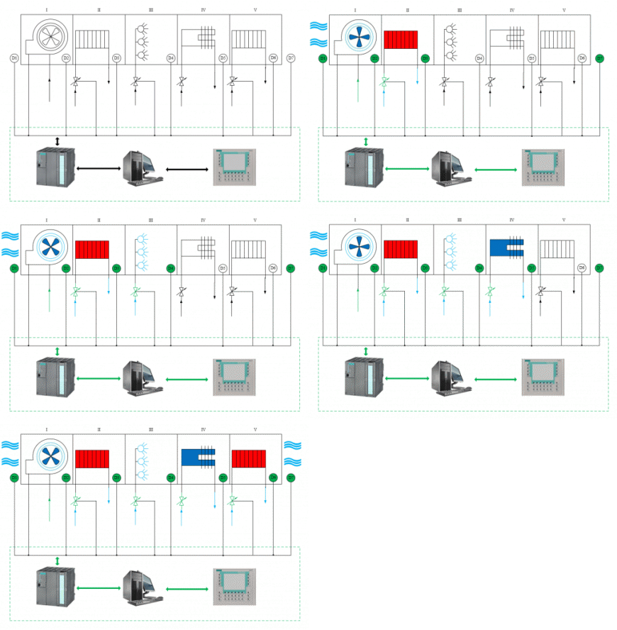
Picture 2 – Model of air conditioning system
(animation: 5 frames, 147 kb, 5 cycles of repetition)
The system works as follows: when applied to the programmable logic controller signal the inclusion of the air conditioning system is made activating all the sensors and other elements open the outer air injection valve section, after which the air is injected by means of a powerful fan. Poll of all sensors occurs, the temperature measurement is made and the surrounding air humidity, and indoor air conditioning system sections. Information on air temperature and humidity is supplied to the programmable logic controller, processed and then, if necessary adjusting if temperature or humidity does not match the value that is entered by the operator, or corresponds to the specified operating mode (Summer / Winter, Day / Night) control signal is supplied to the actuators, which immediately opens a valve to supply water to the tube as much as is necessary to achieve the required temperature and humidity. For air temperature and humidity monitor temperature sensor TE and ME humidity sensors in the scheme are marked with the D complexes, each complex has its own numbering. It starts heating, cooling or air humidification. Upon reaching the desired temperature and humidity the water supply valve is closed for as much as necessary to maintain the temperature and humidity. Signal supplied to the actuators. At the same time change the mode of operation, zhelayumuyu temperature or humidity can be using the server (computer) or HMI control panel on which specific software is installed. When parameters are changed, one of the two devices is signaled immediately to the controller, which adjusts the parameters of the air conditioning installation sections. Communication between the controller, the server (computer) and HMI panel is carried out by means of Industrial Ethernet. If desired, can be connected via Profibus DP.
4.3 Simulation control system
At this stage, it is considered only heating and cooling section, humidification section wakes developed in the further implementation of the master's work. Simulation of the system wake up spending based on perturbation. It refers to a perturbation of the outer air temperature. Define the input signal is equal to 25 °C, as well as a disturbance in the temperature jump is 10 °C. Based on the theory of automatic controll and to simplify the analysis of the graphs will take input equal to 1, and the indignation equal to 0.3. Accordingly 1 equal to 25 °C, and 0.3 equal to 30% of 25 °C, that о ≈ 10 °C. In the simulation, we rely on the fact that when the system is sharp and large temperature jump, it also deal with the rest of the disturbance.
circuit simulation in Simulink package construct based on a block diagram of the control system for the sections of the heating and cooling of air.
Perform simulation of air heating section:
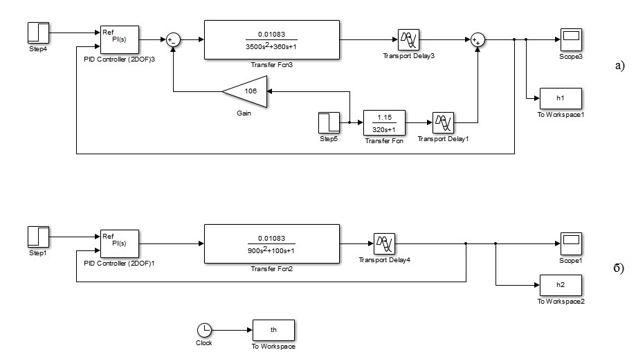
Picture 3 – Circuit simulation of the heating section: а) air temperature control system in a room, б) control the air temperature at the installation output system
Perform simulation of the system with the received control settings.
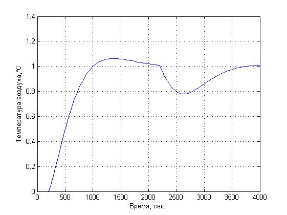
Picture 4 – Schedule changes in air temperature with the applied perturbation
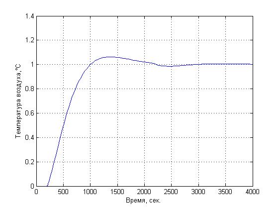
Picture 5 – Schedule changes in air temperature with the applied perturbation and connected compensator
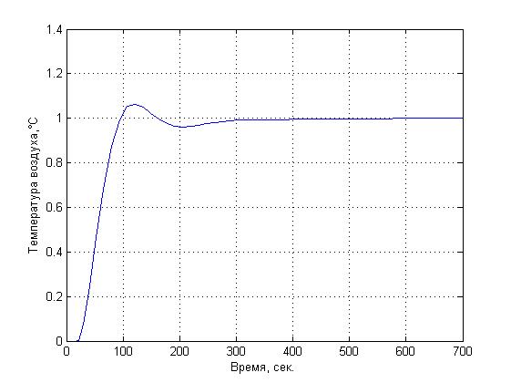
Picture 6 – Schedule changes in temperature at the outlet of the installation
Perform simulation of air cooling section:
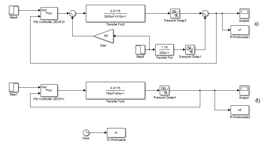
Picture 7 – Circuit simulation of the cooling section: а) air temperature control system in a room, б) control the air temperature at the installation output system
Perform simulation of the system with the received control settings.
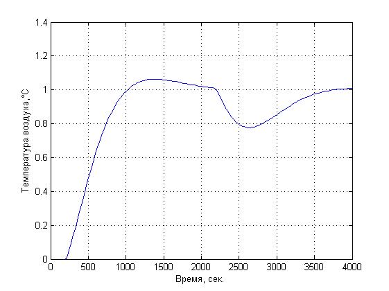
Picture 8 – Schedule changes in air temperature with the applied perturbation
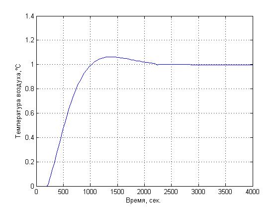
Picture 9 – Schedule changes in air temperature with the applied perturbation and connected compensator
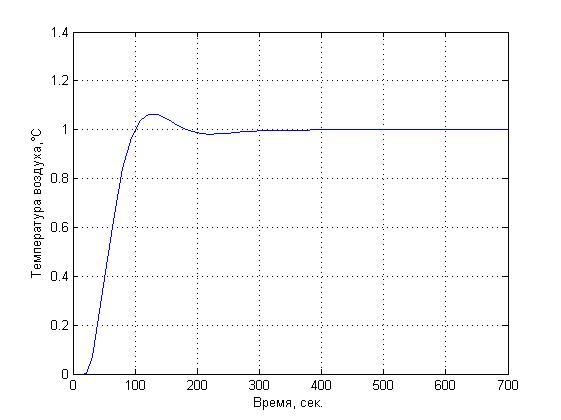
Picture 10 – Schedule changes in temperature at the outlet of the installation
Let us analyze the above mentioned plots: pic. 4, 8 graphs of temperature versus time, we can observe the operation of the system filed with indignation. It can be seen that overshoot is not more than 10%, that fully satisfies the requirements of the system in such a sharp jump. The graphs can be observed that the external disturbance was applied, namely environmental temperature drop at a time environment. Further, in Fig. 5, 9 shows graphs of the compensator system. After analyzing them observe that the overshoot is also no more than 10% and the system copes with indignation properly. The graphs in pic. 6, 10, we can analyze the quality of the temperature change at the outlet of the installation. Override system is not more than 10% and the system copes with the task.
Our task was to assess the quality. Were selected requirements:
- Overshoot less than 20%;
- Transient time for the system parameter based on the room no more than 60 minutes (3600 sec), Excluding a system parameter space no more than 10 minutes (600 sec).
Analyzing the above presented graphics can conclude that the system fully meets the above listed quality criterions.
Conclusions
As a result of the analysis of modes of air ka automatic control facilities of air conditioning systems formulated requirements for SCR control system, the distinctive feature of which is to centralize the control and interconnection of all plant sections.
The analysis of the existing installation section control systems local type of ACS was selected. A new method for automatic control of the air conditioning unit, namely the implementation of the data sharing options. Air between the sections and the calculation based on the recipes of these data.
In the justified and developed technical solutions for the management of the system using programmed logic controller.
In writing this essay master’s work is not yet complete. Final completion: May 2017. Full text of the work and materials on the topic can be obtained from the author or his manager after that date.
List of sources
- Р. Дорф, Р. Бишоп Современные системы управления. – М.: Лаборатория Базовых Знаний. – 2002 – 832 с.
- Ч. Филлипс, Р. Харбор Системы управления с обратной связью. – М.: Лаборатория Базовых Знаний, 2001 – 616 с.
- Е. С. Бондарь, А. С. Гордиенко, В. А. Михайлов, Г. В. Нимич Автоматизация систем вентиляции и кондиционирования воздуха. Издательство Аванпост‑прим, 2003. – 561 с.
- В. А. Лукас Теория управления техническими системами. Учебный курс для вузов. Екатеринбург: Издательство УГГГА, 2002. – 675 с.
- А. Л. Нестеров Проектирование АСУТП. Методическое пособие. Книга 1. – СПб.: издательство ДЕАН, 2006. – 552 с.
- А. Л. Нестеров Проектирование АСУТП. Методическое пособие. Книга 2. – СПб.: Издательство ДЕАН, 2009. – 944 с.
- Simatic S7. Технические данные. Интернет издание, 2009г. – 539 с.
- Simatic Touch Panel. Технические данные. Интернет издание, 2009г. – 80 с.
- А. Г. Сотников Автоматизация систем кондиционирования воздуха и вентиляции. – Л.: Машиностроение (Ленингр. отд–ние), 1984.
- А. С. Клюев, А .Т. Лебедев, С. А. Клюев, А. Г. Товарнов Наладка средств автоматизациии и автоматических систем регулирования: Справочное пособие, Под ред. А. С. Клюева. – 2‑е изд., перераб. и доп. – М.: Энергоавтомиздат, 1989 г. – 368 с.
