
Abstract on the theme of master's work
Содержание
- Introduction
- 1. Relevance of the topic
- 2. The purpose and objectives of the study, the planned results
- 3. Advantages of microprocessor complexes.
- 4. Selecting the type of terminals
- Conclusion
- List of sources
Introduction
Recently, one of the important problems in the domestic energy sector is the replacement of an outdated equipment park at power plants and substations of electric power systems (EPS). Thus, the operation of outdated relay protection complexes may lead to false protection triggers or even their failure, which in turn will lead to the development of dangerous emergency situations and a decrease in the reliability of the operation of the EPS as a whole.
1. Relevance of the topic
The GPP was built in 1971. Since then, capital repairs have been carried out periodically there, at intervals, testing of protection and high-voltage testing of equipment. Spare parts were changed only if this was necessary.
As for the switchgear 6 kV, the 6 kV oil circuit breakers of the VMG-133 and VMP-10 type are now discontinued, there are difficulties with the purchase of spare parts for circuit breakers, in addition, they are morally obsolete. The drives used to control the VMP - 10, type PP - 61 are also morally obsolete, besides they have developed their switching resource. At the moment, there are difficulties in adjusting the drives. Therefore, we take a decision to replace obsolete oil circuit breakers of the VMG-133 type and drives of the PP-61 type with more modern vacuum switches with electromagnetic drives.
All this predetermines the relevance of the topic of replacing, reconstructing and upgrading relay protection complexes in order to improve the reliability of the operation and the ability to transfer information from a low to a higher level of the hierarchy of automated process control systems (APCS), as well as the possibility of automatic and remote control It is suggested to investigate the scheme of the electrical network of substation "GPP 35/110 kV" and to work out the main issues of modernization of relay complexes protection of power transformers and outgoing lines.

Drawing 1 - Scheme of electricity supply to the GPP (animation: 7 frames, always repeated, 142kilobytes)
2. The purpose and objectives of the study, the planned results
At the first stage of the project, it is necessary to give general information about the design object, which include a description of the main circuit of the electrical power circuits, and the designation of the substation in the district power system.
Further, according to the loads of substation connections, a choice of power transformers and auxiliary transformers should be made. In addition, it is necessary to calculate all types of short-circuit currents (KZ) and, based on the results of the calculation, check the selected equipment, set up the relay protection of the substation.
The main issue of the diploma project is the upgrade of the relay protection complex of the substation, for which it is necessary to make detailed calculations of the pickup parameters of the selected more modern transformer protections and outgoing power lines on the semiconductor and microprocessor element base.
3. Advantages of microprocessor complexes.
Advantages of microprocessor complexes.
The use of methods and technical means of information processing by digital computers in the Relay Protection and Automatic Equipment has led to the creation of integrated complexes that perform all the functions of traditional devices of relay protection and automation devices and possess broad informational properties and service capabilities that significantly improve the reliability and efficiency of the operation of technical means for automatic control of electric power installations.
Digital microprocessor systems are intelligent technical means. They have important positive properties that are not found in analog devices:
• multifunctionality and small dimensions: one digital measuring relay replaces several analogue relays;
• remote changes and checking of settings from the operator control panel;
• Adaptation to the EPS regime - automatic adjustment of the RPA settings when changing the scheme and mode of operation of EPS;
• Continuous self-diagnostics and high hardware reliability;
• registration and memorization of emergency parameters;
• remote transmission to the operator of information on the status and operation of relay protection devices;
• Reduction of special maintenance - periodic checks of adjustment and serviceability of relay protection devices.
4. Selecting the type of terminals
To protect the substation, we will use the terminals of the firm "Bresler", Cheboksary. Today, the Bresler Information Center is one of the few Russian companies able to perform a full range of works both in Relay Protection and Automatic Equipment and on automation of technological processes for substations of all voltage levels and ready for implementation of projects on complex equipment of substations. The manufactured devices have a great application practice at the enterprises of the power system, as well as at the enterprises of the metallurgical, chemical, machine-building and oil-and-gas complex.
The devices are designed for installation in CSR, KRU, KRUN, KTP of CH of electric stations and substations, as well as on panels, in control cabinets located in relay halls and control panels. The devices provide interaction with low-oil, vacuum, SF6 circuit breakers equipped with various types of drive mechanisms. The devices are designed to be used as the main and backup protection of various connections, in the form of stand-alone devices or together with other devices of the relay protection and automation devices, performed on various element bases (including on the electromechanical element base).
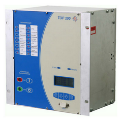
Drawing 2 – Appearance of terminals TOP 200
The TOP-200 devices are made using a microprocessor-based element base. The use of a microprocessor element base ensures consistency of characteristics, high accuracy of measurements, as well as the possibility of implementing various algorithms for automation, control, protection functions (including and at the request of the Customer). The devices are a set of blocks, structurally combined in a 19 inch cassette of the European standard. In the upper part of the faceplate there are 16 LEDs for signaling the operation of protections (in the TOR 200-BTS 32 LED version). At the bottom of the front plate display and control elements are located, as well as a liquid crystal display with four control buttons and a communication port with a laptop computer. LEDs "Faulty" and "Upit" are located above the display. The units are installed on the back of the devices (after removing the back plate) into the connectors on the integrated board. On the blocks are the output connectors of the blocks for connecting external circuits (power circuits, circuits of the tower, signal and output circuits), as well as the ports of communication with the process control system. The grounding bracket is also located on the back of the device and is marked.
The device includes the following units:
• power supply unit with circuits of input discrete signals and output relays;
• block of analog input signals;
• blocks of input discrete signals and output relays (in some versions separate input and relay);
• Central Processing Unit;
• The interface unit.
The terminals of the "TOP 200" series are operated from a source of constant, alternating or rectified operational current. The range of supply voltages is from 24 to 220 V (to be specified when ordering).
The device "TOR 200" is not damaged and does not trickle when the power source is turned on and / or turned off, after power interruptions of any duration, followed by restoration, when the DC voltage is applied in reverse polarity, and also in the case of ground faults in the network direct current or rectified current.
The electronic part of the device is galvanically isolated from the operational current source. the device remains operative without changing the parameters and characteristics of the operation if the ripple current in the voltage is up to 12% (up to 35% at DC) of the average value and power interruptions not exceeding 0.5 s.
It is allowed to use the TOP-200 device in relay protection circuits on alternating operational current without redundancy. the readiness time is not more than 0.25 s.
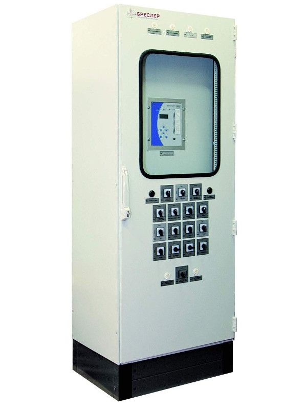
Drawing 3 – Cabinet appearance
The TOP 200 device provides:
• Local control from the buttons on the front panel or from the keys on the door of the relay cabinet, as well as remote control from the ACS TP by any type of switch;
• Blocking from multiple switch insertions;
• Monitoring of control circuits (RPO, RPV, SF6 gas pressure, automatic switchgear);
• Self-locking of the trip circuit;
• Prohibition of switching on when the Shifter is deactivated and the switching circuits are malfunctioning;
• Ability to act on the second coil circuit breaker;
• I / O from any of the protection stages by using software switches;
• Selecting the directional or non-directional action of step protection;
• Configure the action of the protections on a signal or turn off by means of a matrix of soft switches;
• Several time delays of current protection stages;
• A set of inverse characteristics for the third (sensitive) stage of the overcurrent protection;
• Breaker current sensing element;
• ATS with power and frequency control on the input switch (power loss protection);
• A special "Test" relay for testing protection without affecting the other output relays.
• Alarm:
• 16 LED indicators (14 of which are reassigned) on the front panel of the device;
• Output signal relays (including and reassignable) with normally open and switching contacts;
• LEDs ON, OFF on the front panel of the device for signaling the switch position;
• Signaling of the protection stages on the LCD.
• Measurement and control:
• Measurement in primary or secondary values;
• Measurement of phase currents;
• Changing the line voltages;
• Measurements of residual current and voltage;
• Measurement of power, energy, power factor;
• Frequency measurement;
• Monitoring the status of digital inputs and output relays;
• Monitoring of switch parameters:
• the time of the last shutdown;
• the time of the last turn on;
• switching resource (by the phase);
• mechanical resource;
• control of SF6 gas pressure.
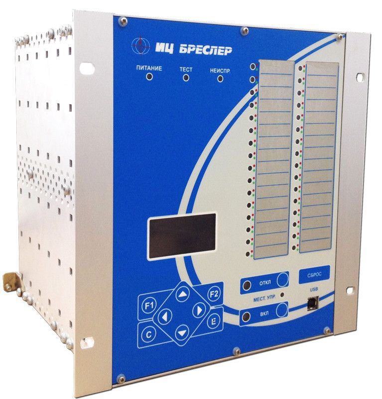
Drawing 4 – Appearance of terminals TOP 200
The device "TOP 200" provides registration and oscillography of emergency values, as well as parameters of the switch. When starting and triggering the protection stages, the following parameters are registered and stored in the non-volatile memory with the full timestamp:
• Phase currents, line voltages, residual current and voltage;
• Duration of the emergency;
• Fixes up to 10 starts / trips of protection stages;
• Up to 250 events with a full timestamp are stored in the non-volatile memory.
Non-volatile memory stores, in addition to the above, the state of internal logic signals, output relays and the state of external signals applied to digital inputs. The built-in alarm recorder has 3 modes of operation: the recording of instantaneous values ??of analog values ??with a sampling frequency of 800 or 1600 Hz, as well as the recording of envelopes of the effective values ??of voltages and currents or the frequency of the network with a sampling frequency of 200 Hz (for individual versions). Waveform recording can be performed by starting or triggering the protection stages, breaker failure protection, when certain functions of the automation function, as well as when the signals are triggered or returned on digital inputs. The total length of the oscillograms for recording 8 analog channels is 45 seconds.
The TOP-200 devices have a single hardware platform and are implemented using unified blocks, which allows the user to minimize the number of spare parts, as well as to facilitate the setup and maintenance of new equipment. The types of blocks in the majority of typologies coincide, which makes it possible to replace them on the spot.
Conclusion
In the diploma project, the issues of reconstruction of the substation are considered. Based on the calculation of electrical loads, as well as taking into account the reliability of power supply, a substation design was developed. The selected modern electrical equipment for all voltage levels is tested for short-circuit currents.
As relay protection and automation devices, microprocessor terminals ТОР 200 for 35 and 6 kV are used. The system of control and accounting of electric power, automatic control system of the GPP is installed. The main parameters of relay protection are calculated.The issues related to ensuring the safety of employees in the enterprise are considered.
List of sources
- ПУЭ. Спб.: Издательство ДЕАН, 2001. - 928 с.
- Шабад М.А. Автоматизация распределительных электрических сетей с использованием цифровых реле: Учебное пособие. - СПб.: Изд. ПЭИпк, 2002.
- Гасаров Р.В., Коржов А.В., Лежнева Л.А., Лисовская И.Т., Проектирование электрических станций и подстанций: Методические указания к курсовому проекту. - Челябинск: Изд-во ЮУрГУ, 2005. - 46 с.
- Комплектные устройства защиты и автоматики серии «ТОР 200» [Электронный ресурс] // URL: http://relematika.ru/produkty/tor_200/tor_200/ (дата обращения: 11.12.2017).
- Нормы технологического проектирования Подстанций переменного тока с высшим напряжением 35 - 750 кВ.
- Схемы принципиальные электрические распределительных устройств подстанций напряжением 35 - 750 кВ. Типовые решения, Энергосеть проект, 2006 г.
- Справочник по проектированию подстанций 35 - 500 кВ/ Г.К. Вишняков, Е.А. Гоберман, С.Л. Гольцман и др.; Под ред.С. С. Рокотяна и Я.С. Самойлова. - М.: Энергоиздат, 1982. - 352., ил.