
Abstract
- Introduction
- 1. Analysis of the state of matter
- 2. Purpose of work
- 3. Scientific novelty
- 4. Practical value
- 5.The main content of the work
- Conclusions
- References
Introduction
With the increasing level of automation in various industries, agriculture and housing and communal services, the increase in the number and increase in the capacity of the objects that are sources of ignition is directly related. As sources of ignition very often perform combustible materials (substances), heated to high temperature parts and components of electrical products, as well as arising in emergency modes electric Arcs, sparks, gas emissions, etc. In these conditions, the main, and often the only way of prevention the fires is the refusal to use ignition sources or reduce their energy to a safe level. In many industrialized countries about 20-25% of the total number of fires occurring annually, constitute fires, arising from a malfunctioning or misusing of electrical devices, while the growth trend of such fires persists [1]. .
1. Analysis of the state of matter
As sources of ignition, electric wiring heated up to a high temperature, as well as accompanying emergency conditions electric arcs, sparks, ejection of gases, etc., very often act. The main reasons for the occurrence of fires: careless handling of fire, violation of the rules of the fire safety while fitting and operating electrical installations, etc.
According to statistics for 2015, the main causes of fires in Russia were: careless handling of fire - 47473 units (32.5% of the total number), violation of the rules for the fitting and operation of electrical installations - 40767 units (27.9%) (Figure 1) and violation of the rules for the fitting and operation of furnaces - 21023 (14.4%) [2]. Electrical products are traditionally one of the most fire-hazardous products. So in all fires that occurred in Russia in 2015 (145.9 thousand units) 9405 people died, in fires resulting from the violation of the rules for the fitting and operation of electrical equipment (40 767 units) 1879 people died.
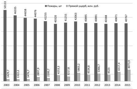
Fig. 1. Data on fires that arose as a result of NPUiE electrical equipment in Russia for 2003-2015.
A similar situation is observed in Ukraine. The Ministry of Emergency Situations of Ukraine calls the main causes of fires that occurred in 2015: careless handling of fire - 56 869 units (71.5%), violation of the rules for the fitting and operation of electrical equipment - 13 098 units (16.5%), violation of the rules for the fitting and operation of furnaces, heat generating facilities and facilities - 4171 units (5.2%) [3]. The total number of people killed in the fires in Ukraine in 2015 was 1947 people, injured - 1360 people. (Figure 2).
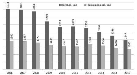
Fig. 2. Dynamics of the number of deaths and the number of people injured in the fires in Ukraine in 2006-2015.
The average annual distribution of fires in electrical installations for reasons of their occurrence, according to the research of All-Russian Scientific Research Institute of Fire Protection, as well as in the works of A.A. Soshnikov [4], which contain the results of an analysis of statistical material recorded by the Altai regional fire department, confirming that the main cause of fires in electrical installations (up to 70%) are short circuits caused by various factors.
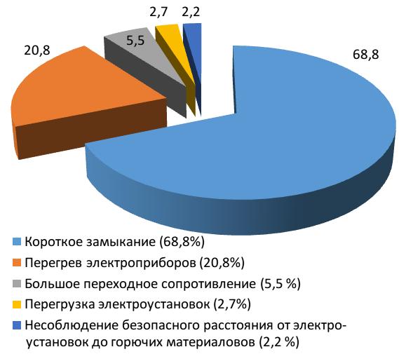
Fig. 3. Causes of fires in electrical installations
As the data shows [5], in Russia, as of 2007, the following types of electrical products occupy leading positions in the number of fires: cable products - wires and cables (63.6%); switches, plugs and other plug-in elements (6.7%). At the same time, the number of fires resulting from the fire of cables is 20-30 times less than the number of fires caused by the fire of wires. Analysis of statistics showed that the number of fires is significantly affected by the location and type of the object on which the fire occurred. Thus, the greatest number of deaths in fires in 2015 was registered in the residential sector of Ukraine - 1919 people (98.6% of the total number of fatalities due to fires). According to the Research Institute of Mine Rescue and Fire Safety Respirator
(Donetsk) in Donetsk region in 2006 the largest share in this segment (82.3%) is occupied by residential buildings and objects of private property.
2. Purpose of work
Scientific substantiation of the process of heating wirings with a voltage of 0.4 kV. Determination of the relationship between their electrical and thermal characteristics, depending on the material of the wire, the core material, the cross-section, the overload factor required to improve the protection devices.
3. Scientific novelty
Obtaining the experimental dependences of the permissible heating time for wirings with a voltage of 0.4 kV; a proposal to improve the protection with a microprocessor release.
4. Practical value
Method for assessing the danger of heating electrical wiring 0,4 kV, used in buildings. To improve the fire protection characteristics caused by electrical reasons.
5. The main content of the work
At the Department of Electricity Supply of Industrial Enterprises and Cities (DonNTU, Donetsk), for protection developing, an analysis of the thermal characteristics of cable and conductor products was carried out. With the help of an experimental stand, the viscosity-temperature characteristic of melting of insulation of two-wire cables (models BBG, AVVG, PPV, APVV, PVS, SHVVP) 1.5-2.5 mm2 cross sections for copper, 2.5-4 mm2 for aluminum was determined. The devices used in the circuit diagram (Fig. 3) have the following technical characteristics. LAT1 - laboratory autotransformer of AOSN-2-220-82 type (voltage regulation limit: 5-240 V at load current up to 2 A); Т1 - power reducing transformer of OSM-0,25 type UZ (power 0,25 kVA, voltage of windings ВН-220, НН-24В); A - current clamp FUKE 266 Clamp meter CE (measuring limit up to 1KA); V1 - clamp meters FUKE 266 Clamp meter CE (with the possibility of measuring the temperature with a thermocouple up to 750 °); V2-universal digital voltmeter V7-38; digital stopwatch.
Fig. 4 shows the characteristic of the circuit breaker of group "C" [7]. Various reasons (preheating the release device, deviation of parameters during manufacture) can lead to a significant variation in the characteristics of the circuit breaker (curves 1 and 2). With a slight deviation of the short-circuit current below the threshold of the trip of the electromagnetic release (point 1 on curve 1), the tripping time of the circuit breaker is determined by the thermal release and reaches 7 s (point 2 on curve 1). When passing through the circuit breaker 5 Iн in the preheated state, the circuit breaker should trip through 0.02 s (point 3 on curve 2), in the cold state with this load it will shut off within 9-20 s (for automata up to 32 A and higher 32 A respectively) - point 4 on curve 1.
Insufficient sensitivity of the circuit breaker can lead to fire-hazardous conditions in the wiring in the event of a failure of the protection of the feeder automatic switch, for example in the case of welding a movable contact to the body of the circuit breaker. In this case, it is necessary to provide long-range redundancy by means of a group circuit breaker.
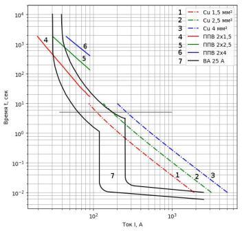
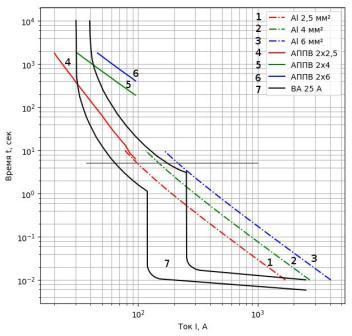
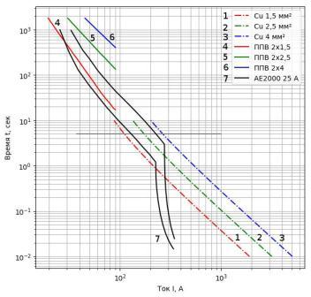
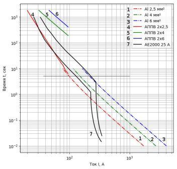
Fig. 4. Combined time-current characteristics of circuit breakers and conductors: а, в - conductors with copper conductors of type ППВ with sections of 1.5-4 mm2; b, d - conductors with aluminum conductors of the type APPV cross-sections 2.5-6 mm2; 1-3 - short circuit currents are obtained by the formulas [8] for the thermally permissible temperature 160° 4-6 - the melting time of PVC insulation under steady-state current, obtained experimentally in [6]
Analyzing the graphs, we can conclude that not all cases of circuit breaker selected in accordance with the PUE provide a timely turn-off at short-circuit. In particular, in clause 3.1.11 of the rules for the fitting of electrical installations it is required to ensure the multiplicity of the rated current of the release circuit breaker (with the unregulated back-dependent characteristic dependent on the current) and the starting current of the release circuit breaker (with a controlled reverse current-dependent characteristic) with respect to the long-term current load of the copper stranded wire, rubber equivalent heat insulation characteristics (Table 2) no more than 100%. The rated current of the release AB (I = 25 A) is matched to the permissible currents of a copper wire of 2 x 2.5 mm2 or an aluminum wire of 2 x 4 mm2 section, as specified in 3.1.11 of the rules for the fitting of electrical installations, but as follows from the data, presented in Fig. 5, the protective characteristics of the circuit breaker can pass above the viscosity-temperature characteristic of these wires. This leads to their likely fire-hazardous heating. The inconsistency of the circuit breaker tripping time for the most frequently used conductors in residential premises was found (1.5-2.5 mm2 for copper, 2.5-4 for aluminum), i.e. for copper stranded wire cross-sections 2.5 and 4 mm2 and APPV cross-sections 4 and 6 mm2 there are separate areas where circuit breaker works for an unacceptably long time. If 1.5 mm2 copper stranded wire conductors and 2.5 mm2 APVV are used (typical for residential areas), then in a wide range of currents protection with circuit breaker (see figure 4) can lead to a fire-hazardous condition of the electrical wiring.
Fig. 5. Schematic diagram of the experimental stand for determining the time intervals before the melting of PVC insulation of cable products VVG (AVVG), PPV (APPV), PVS, ShVVP with different multiplicity of overloads (animation: 8 frames, 3 repetition cycles, 42.4 kilobytes)
Thus, in existing 0.4 kV networks protected by standard circuit breakers that respond to overload and short-circuit currents, in order to increase the level of fire safety, it is necessary to develop more advanced protections, based on microprocessor releases, that would solve the following tasks:
- increasing the sensitivity of circuit breaker;
- taking into account the characteristics of the protected lines;
- detuning from arc closures, which have intermittent character;
- forecasting the heating of the cable (wire) to be protected from the value of the total current.
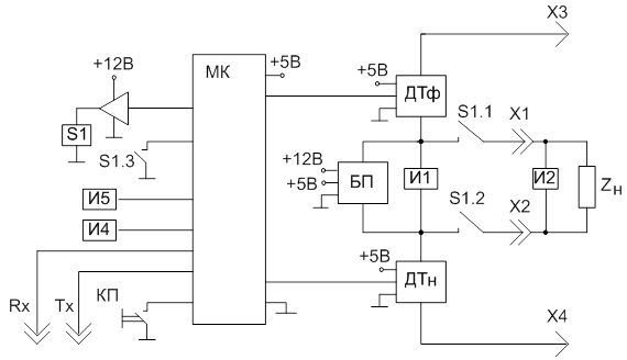
Fig. 6 - Block diagram of microprocessor protection. Notation: DTF, DTN - phase and zero current sensors; - MC - microcontroller family STM; PSU - power supply; S1 - contactor; Zн - load; КП - the button "START"; И1, И2, И4, И5 - indication elements; X1, X2, X3, X4 - load connection terminals; Rx, Tx - the outputs of the serial interface of the UART standard.
Conclusions
The devices used to protect the device have a number of drawbacks due to the timing of disconnection of the short-circuit protection systems or overloads with permissible temperatures of heating the conductors of the wires, and also to a decrease in the sensitivity to remote and arc faults. The analysis of the possibilities of microprocessor protection devices demonstrates the advisability of developing new principles for ensuring fire safety of cables and wirings of 0.4 kV networks that would allow accelerating the disconnection of the emergency area, reducing the probability of overheating, melting of insulation and splashing of metal particles. One of the most important and effective ways to reduce the fire hazard in electrical distribution and group networks of buildings is the use of a new generation of cables (VVGng, VVGng-LS): non-burning, low smoke-evolving, fire-resistant, with low toxicity of combustion products.
References
- Смелков Г.И. Пожарная безопасность электропроводок, — М.: ООО
КАБЕЛЬ
, 2009. — 328 с. - Официальный информационный сервер Государственной службы Украины по чрезвычайным ситуациям: http://www.dsns.gov.ua/. [Электронный ресурс]
- Пожары и пожарная безопасность в 2015 году: Статистический сборник. Под общей редакцией А.В. Матюшина. - М.: ВНИИПО, 2016 – 124 с.: ил. 40.
- Рябинин И.А. Основы теории и расчета надежности судовых электроэнергетических систем, - 2-е изд. – Л.,
Судостроение
, 1971. – 456 с. - Прогнозирование, мониторинг и предупреждение возникновения источников возгорания горючего материала в электрифицированных помещениях [Текст] : дис. ... канд. техн. наук : 05.26.01 / Солёная Оксана Ярославовна ; ГВУЗ "Донецкий национальный технический университет". – Донецк, 2014. – 215 с.
- ГОСТ Р 50345-99 (МЭК 60898-95). Автоматические выключатели для защиты от сверхтоков бытового и аналогичного назначения. — Взамен ГОСТ Р 50345-92; введ. 01.01.2001 — М.: Госстандарт России — 65 с.
- ГОСТ Р МЭК 60949-2009. Расчет термически допустимых токов короткого замыкания с учетом неадиабатического нагрева. — введ. 26.06.2009 — М.: Госстандарт России — 12 с.
- Правила устройства электроустановок. – М.: Кнорус, 2015. – 488 с.