
Abstract on the theme of master's work
Content
- Introduction
- 1. Aims and objectives of the study
- 2. The main issues that need to be addressed in this paper
- 3. Review of research and development
- 4. Overview of the stand elements
- 4.1 DC Motor
- 4.2 Thyristor converter
- 4.3 The debug board stm32f4
- 5. Automatic control system
- 5.1 Mathematical description of the DC motor of independent excitation
- 5.2 Negative Feedback
- 5.3 Slave control of coordinates
- List of sources
Introduction
Currently, the use of an uncontrolled drive is extremely rare even in consumer devices, not to mention the industry, where asynchronous motors with frequency converter control are used for the most part. However, DC drives have already won their specific niche and will be in demand for a long time.
The control systems for both AC and DC motors are usually built on the basis of subordinate control systems. Understanding the principles of construction and operation of such systems is best starting with the study of a DC electric drive, and only then move on to more complex systems based on AC motors.
The DC motor is divided into several types:
1. DC machines with series and mixed excitation – are used mainly in traction electric drives, since they have an increased torque with respect to motors with parallel or independent excitation. However, starting of such engines can not be carried out without load.
2. Direct current machines with independent and parallel excitation – can be controlled not only by changing the voltage of the anchor chain, but also by controlling the current of the field winding, the so-called two-zone regulation.
3. DC machines with permanent magnets differ from machines with independent excitation with increased reliability, simplicity, and also reduced power consumption. After all, excitation is not due to energy from the network, but due to the magnetic field of permanent magnets. However, in this case, in comparison with a DC machine with independent excitation, it is not possible to control the speed of the motor along the excitation circuit.
4. The brushless DC motors differ from the classic DC machines by the lack of a collector-brush mechanism, due to which, they have an increased life, and also such engines are considered high-speed ones.
Thyristor converters serve as the regulated power sources for direct-current motors in industry, however, if the system is of low power, then the use of pulse-width modulation based on transistors is possible. In the work presented, the first version of the source of the regulated voltage is applied. Of course, it is obsolete. However, this has no influence on understanding the basics of building subordinate control systems, since such systems can include both thyristor converters and PWM transistor modules (which are more rapid). The difference is only in the form of the input reference signal, which we will send to these devices.
1. Aims and objectives of the study
The purpose of this work is to create a laboratory bench for the study of subordinate speed control systems based on a DC motor using, as a control element, the microcontroller STM32f4, as well as the mathematical modeling application package MATLAB. The study will help to consolidate the knowledge gained in the study of the discipline "Control systems of electric drives" on a real installation, for a better understanding of the management processes and the creation of systems of subordinate regulation.
2. The main issues that need to be addressed in this paper
- Selection of sensors for automatic speed control;
- Connection of the STM32f4 microcontroller and the entire periphery to the existing stand;
- Development of subordinate speed control system;
- Adjustment of system controllers;
- Development of a system of protection against improper adjustment of controllers.
3. The structure of the stand for the study of ATS
The laboratory stand includes DC motor with independent excitation of PBST 32 with the complete tachogenerator, thyristor converter BTU 3601, galvanic isolation for protection of control system, microcontroller stm32f4 with current and voltage sensors, computer with MATLAB mathematical modeling package installed.
4. Overview of the elements of the power section of the stand
4.1 DC Motor
The DC motor is a synchronous machine, in which the functions of the stator and the rotor are reversed. The stator creates a constant magnetic field, and the rotor, rotating in this field, converts electromagnetic energy into a mechanical one. In the rotating rotor, the brush assembly performs the function of changing the current direction when moving the conductors of the rotor winding to the opposite pole of the stator winding. [ 1 ]
According to the power scheme, DC machines are divided into machines with independent (Figure 1.1a), parallel (Figure 1.1b), sequential (Figure 1.1c), mixed excitation (Figure 1.1d), as well as machines with magnetoelectric excitation (Figure 1.1 e).
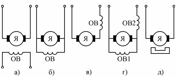
Figure 1 – Options for connecting the field winding
This bench uses a motor with an independent excitation winding. In this motor, the field winding is connected to a separate power source, so that the current in the excitation winding does not depend on the armature current.
The mechanical characteristics of a DC motor with independent excitation are linear and cross the ordinate axis at the point of idling n0.
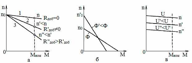
Figure 2 – Mechanical characteristics of the DC motor of independent excitation
Also, the machine with independent excitation has the possibility of two-zone speed regulation. As the excitation winding current decreases, the motor speed increases, but the power remains unchanged, thereby reducing the torque. Such control is widely used, for example, in crane mechanisms, when it is necessary to carry out a rapid movement of the working body of the crane without the load. [ 2 ]
The motors of the PBST series are manufactured with independent excitation, without a stabilizing series winding. Stable operation of the electric motors PBST is provided by the drive control circuit.
The motors of the PBST permit the regulation of the speed of rotation upwards from the nominal (at constant power) weakening of the field of the main poles or in short-time modes with a duration of no more than 5 minutes at full flow – a change in the voltage at the anchor. At the same time for the PBST motor with a voltage of 220 V, an increase in voltage is possible at a nominal armature current up to 330 V. The speed of rotation of the PBST 32 engine should not exceed 4000 rpm. The engines allow operation at low speeds (0.5 -1.5 rpm) with nominal excitation and torque not exceeding the rated speed.
Electric motors PBST – reversible. The permissible number of reverses per hour is not more than 400, provided that the rms current of the armature does not exceed the rated current. The difference in the rotational speed of the DCB motor with a change in the direction of rotation (at rated load, voltage and excitation current) should not exceed 5%. [ 3 ]
4.2 Thyristor converter
Thyristor DC-to-DC converter is a device for converting AC to DC with regulation of output parameters (current and voltage) according to a given law. Thyristor converters are intended for supplying the armature circuits of the motors and their excitation windings.
Thyristor converters consist of the following main components:
- Transformer or current-limiting reactor on the AC side;
- Rectifier blocks;
- Smoothing reactors;
- Elements of the control system, protection and signaling.
The use of thyristor DC converters makes it possible to realize practically the same characteristics of an electric drive as when using rotary converters in generator-motor systems, i.e., to regulate the rotation frequency and motor torque within wide limits, to obtain special mechanical characteristics and the necessary character of the transient processes at starting, braking, reverse, etc. [ 4 ]
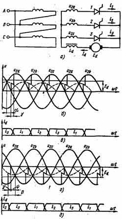
Figure 3 – Three-phase zero circuit (a) and diagrams of current and voltage variation in rectifier (b, c) and inverter (r, g) modes
The power part of the converter BTU 3601 includes: a reversible bridge thyristor converter, a smoothing choke and a matching transformer. It is conventionally accepted that the rectifier H
works on the back
direction and is assembled on the thyristors V1-V6, and the rectifier B
, containing the V7-V12 – in the forward
direction. Set B
and H
are two three-phase bridge circuits, included in parallel.
Protection of thyristors from switching overvoltages is performed by RC-circuits connected in parallel to each thyristor. Since thyristors of different sets are connected in pairs in parallel, there are only six RC-circuits of this kind.
With the help of AC transformers (T2-T4), the rectified current signal of the converter is formed, galvanically isolated from the power circuit. [ 5 ]
4.3 The debug board stm32f4
The stm32f4 debug card is based on the ARM Cortex-M4 32-bit microcontroller, the ST-Link programmer is installed on the board with three different interface ports: a virtual COM port, a storage device and a debugging port.
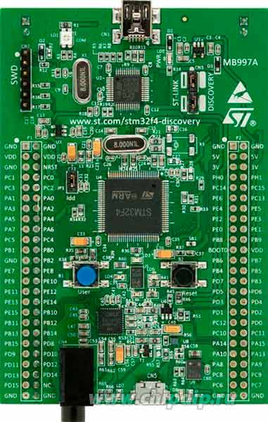
Figure 4 – The debug board stm32f4
The board is powered via USB or from an external 5V power supply.
The frequency of the microcontroller is 168 MHz, this performance is more than enough to control the motor in the automatic control system. [ 6 ]
5. Automatic control system
From the point of view of control, the DC motor is the ideal converter of electrical energy into a mechanical one. The magnetic flux of such a motor is set by a separate winding, and the voltage applied to the anchor circuit is divided into an EMF, a drop in the active resistance and a component of the current change in the armature inductance. To obtain the power drawn from the network, it is necessary to multiply the voltage at the armature by the current, and to obtain the power on the motor shaft it is necessary to multiply the EMF and the current.
At the present time, the system of subordinate coordinate adjustment in the system controlled converter-motor
has already become classical, but other control methods, such as relay control of the output coordinate, modal control, and high-frequency drives use prediction structures. [ 7 ]
5.1 Mathematical description of the DC motor of independent excitation
The DC motor armature current is determined by its EMF (Е a ), armature resistance (R a ) and inductance (L a ).
The electromotive force is expressed by the dependence E = kФω
- Ф – magnetic flux of the engine
- ω is the angular velocity
- k=pN/(2πa) is the design factor of the motor, where p is the number of pole pairs, N is the number of active conductors of the armature winding, and a is the number of parallel branches of the armature winding.
The average value of EMF anchors E I = kFωcp;
Electromagnetic moment M = kFI;
Voltage motor armature circuit is represented as: U i = R i I i + I i (dI i / dt) + E i ;
Voltage equation U = E + IR, where R = R I + R d – impedance circuit armature;
Electromechanical characteristics of ω (I): ω = (U-IR) / (kF);
The mechanical characteristic ω(М): ω = U / (kF) -MR d / (kF) 2. [ 7 ]
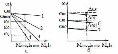
Figure 5 – The mechanical characteristics of the DC motor for various resistances of the armature circuit (a) and voltages (b)
5.2 Negative Feedback
To stabilize any value in the theory of automatic control, negative feedback is usually used. This method of regulation is that there is some given value of the quantity that we want to get. Then for this task the determining influence on the control object is determined, under the action of which it leaves the state of rest and begins to strive for a given value. So, in the process of approaching the state variable of the control object to the set value, the error signal decreases between the reference signal and the real value of the controlled quantity, then the control action on the control object decreases. Ideally, steady-state equilibrium will be achieved at the moment when the task is equal to the controlled state variable. [ 7 ]
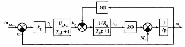
Figure 6 – DC electric drive with negative speed feedback
5.3 Slave control of coordinates
The most common and well-known method of adjusting the coordinates of the electric drive is now a sequential correction with subordinate coordinate control. This technology is applicable not only to DC electric drives, it is used in an asynchronous electric drive with vector control, servo drives with synchronous motors, etc.
The method of sequential correction is based on the fact that the transfer functions of two consecutive links are multiplied and, if a link with a specially selected transfer function is placed in front of the control object, it is possible to obtain a certain result of their multiplication that will have the static and dynamic characteristics we need.
Let the control object have the transfer function W o.p (p), and the desired transfer function of the open system is W. x (p), then the regulator function can be calculated as follows:
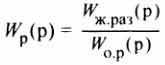
Indeed, if a regulator with a transfer function calculated through this expression is sequentially connected to the control object, then the system shown in Fig. 7a will be reduced to the system of Fig. 7b.
Figure 7 – Sequential correction of coordinates
It should be noted that not every desired transfer function can be realized. So, the converter, feeding the engine, though it seems to be an inertial link, actually contains a delay link. In addition, we can obtain, for example, a given current in the motor armature instantaneously, since its rate of increase is determined by the armature inductance and the voltage that your converter can give out. This means that it is impossible to obtain the desired value directly at the output purely for technical reasons, and, therefore, it is necessary to find a compromise choice of the desired transfer function. [ 7 ]
Let us consider an example of constructing a multi-loop subordinate control system.
The control object is represented as consecutively connected links W об1 (p), W об2 (p), W об3 (p), etc. with the intermediate coordinates x 1 , x 2 , x 3 , ... and the adjustable (output) coordinate X (see the block diagram in figure 8. The coordinates used are the coordinates such as current, voltage, EMF, magnetic flux, moment , speed, position.
To manage each coordinate, a separate loop is organized with its feedback and its regulator. In Fig. 8 the coordinate sensors are represented by links with transmission coefficients K x1 , K x2 and K x , and the transfer functions of the regulators are denoted respectively by W R1 , W R2 and W R3 .
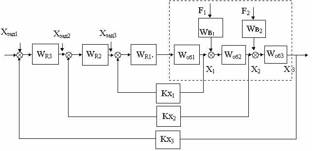
Figure 8 – Multi-circuit subordinate control system
The closed control loops form a system in which an internal circuit consisting of a regulator WR1 first link Wob1 object and the feedback circuit to the coordinate X1, the first external circuit comprising an internal circuit, a second link object W ob2 regulator W R2 and the feedback circuit the coordinate of X 2 and the second outer contour including the first outer contour, the third link of the control object W ob3 , the regulator W R3 and the feedback in the coordinate X 3 , for the case under consideration being adjustable, i.e. X 3 = X.
The output signal of the regulator of each external circuit is the master for the subsequent circuit enclosed inside it. Thus, each internal control loop is subordinated to the corresponding external control loop.
Subordinate control systems are characterized by better control quality than single-circuit systems for the following reasons:
- perturbations, F 1 (p), F 2 (p), arriving at the parts of the object, located closer to the input, before affecting the output coordinate X (adjustable variable) are previously "attenuated" in the internal circuits;
- the presence of internal circuits reduces the effect of changing the parameters of the input part on the dynamic properties of the system (the sensitivity of the system decreases to a change in the parameters of the object);
- the behavior of the controlled variable X becomes faster (less inertial) if the inner contour provides faster own motions than the original ones.
The advantages of the system of subordinate regulation can be attributed
- simplicity of adjustment and adjustment (each circuit includes a regulator, due to which certain dynamic properties are given, standard characteristics are obtained). The adjustment during the adjustment is carried out starting from the internal circuit. Since the regulator has a fairly simple transfer function, and the tuning quality can easily be estimated from the comparison of the loop response to the control jump with the standard transient response, the system setup is simple.
- the convenience of limiting the maximum values of the internal (intermediate) coordinates of the system (since the output signal of the external loop controller is a reference for the internal loop, is achieved by limiting the output signal of the external loop controller)
The disadvantage is some loss in speed, associated with a sequential impact on the object through internal circuits, and not immediately through the input link of the object. [ 8 ]
Список источников
- Усольцев А.А. Общая электротехника: Учебное пособие. – СПб: СПбГУ ИТМО, 2009. – 301 с.
- Теория электродвигателей постоянного тока – электронный ресурс. Режим доступа:
electrikam.com
- Электродвигатель постоянного тока серии ПБСТ – электронный ресурс. Режим доступа:
elektro-dvigateli.ru
- Теория тиристорных преобразователей – электронный ресурс. Режим доступа:
nntu.ru
- Тиристорный преобразователь напряжения БТУ 3601 – электронный ресурс. Режим доступа:
electricalschool.info
- Отладочная плата STM32F4 – электронный ресурс. Режим доступа:
st.com
- Анучин А.С. Системы управления электроприводов: учебник для вузов. – М.: Издательский дом МЭИ, 2015. – 373 с.
- Системы подчиненного регулирования – электронный ресурс. Режим доступа:
ets.ifmo.ru