
Abstract
Content
- Introduction
- 1. Theme urgency
- 2. Purpose and objectives of the study
- 3. Comparative analysis of different types of sensors
- Conclusion
- References
Introduction
In the electric drive for realizing feedback on current and voltage, high-speed precision current sensors are needed ensuring galvanic isolation of power circuits and control circuits [1]. The sensor is most simply realized on the basis of a shunt connected in series to the circuit of the measured direct current, or the divider - in parallel. For potential separation of the input and output circuits of the sensor, the voltage taken from the shunt is converted into an alternating current by means of a modulator. The alternating voltage, modulated in amplitude, is fed to the amplifier input via a galvanic isolation cell. Then it is converted into a constant voltage by means of a demodulator. The pulsating voltage at the demodulator output is smoothed by the filter and fed to the input of the analog-to-digital converter.
As the primary sensors can also be used Hall sensors, included in various schemes, which makes it possible to increase their sensitivity and linearity. Also in the electric drive it is possible to use current and voltage sensors on the Hall effect of the compensating type. Both of these sensors have a galvanic isolation.In the paper, the possibility of identifying the current and the load voltage of the inverter by voltage and current at the inverter input is considered.
1. Theme urgency
Current and voltage sensors on the Hall effect are of a high cost. Therefore, the task of reducing the number of sensors for forming feedback is actual.
2. Purpose and objectives of the study
The purpose of the master's work is to identify the current and load voltage of the inverter using the current and voltage at the inverter input in the drive.
The main objectives of the study:
- Comparative analysis of different types of sensors.
- Selection of the microcontroller and the hardware of the inverter.
- Investigation of control algorithms for an autonomous voltage inverter in an electric drive.
- Simulation of the algorithm for identifying the current and voltage of a three-phase voltage inverter.
- Preparation of a laboratory stand for the identification of current and voltage loads of a DC electric drive and a single-phase voltage inverter.
3. Comparative analysis of different types of sensors
The easiest way to measure current is to place a small resistance in the circuit where you need to measure, and measure the voltage at this small resistance. The measuring resistors Rs are called shunts. Examples of current measurement with shunts installed in the inverter racks and in the inverter DC link (Figure 1) [Anuchin].
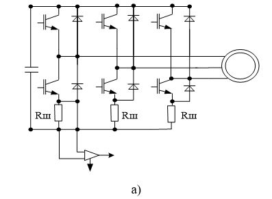
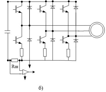
Figure 1 - Options for installing shunts for measuring currents
In (Fig. 1a), the values of the load current can not be obtained at any arbitrary time, since the current flows through the shunt only when the lower transistor in the rack is closed. The measurement can be performed by examining the values of the duty ratio in the racks for a particular PWM period.
It is more difficult to measure if only one shunt is installed in the DC link (Fig. 1, b). Then, in the interval from the beginning of the PWM period to the instant t1, all currents are closed in the upper keys of the inverter and a zero signal comes from the shunt (Fig. 2). Beginning with t1 and ending with t2, the current of phase A flows through the shunt, the measuring amplifier shown in Fig. 1.7, will measure it with the opposite law. In the interval from t2 to t3, the total current of phases A and B flows through the shunt, which is measured with the opposite sign, numerically equal to the current of phase C.
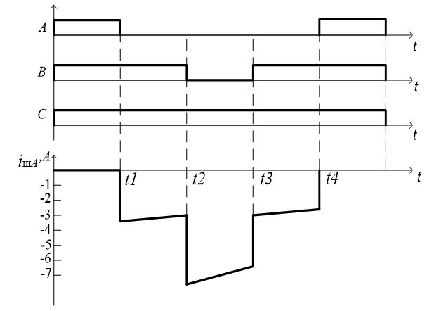
Figure 2 - Phase current measurement curves with a single shunt in the DC link
In such implementations, the microcontroller control system must monitor the output parameters of the PWM module program and determine the moments when the phase current measurements can be reliably performed. Then, for each possible key switching law, a set of rules is analyzed that determine how to interpret the readings of the measured shunt current and calculate the current of each phase. In addition, one must be able to exclude narrow pulses in the states of the inverter and to deviate from the beginning of the next state of the inverter, so as not to fix the interference associated with switching processes.Actually Figure 2 shows the process that is subject to this study.
Measuring currents with shunts has the following advantages:
- Low price.
- Compact wiring and minimum volume.
as well as shortcomings:
Measuring current transformers [1].
With an increase in power above 1 kW, shunt sensors can not be used due to the increasing level of interference from the control system communication to the DC link bus, so they switch to galvanically isolated current sensors. Current transformers are a cheap solution, but they can accurately measure current at frequencies above 15 Hz. Therefore, their application is impossible for most AC and DC electric drives.
Sensors on the Hall effect [1]
Sensors on the Hall effect lack the disadvantages that are present in current transformers. Principle of operation of the Hall sensor: when a current flows along a conductor near a semiconductor element, a field appears around the conductor that permeates the conductor. If through the element to pass the calibrated current, the moving charges will shift under the influence of the electromagnetic field and a potential difference will appear at the edges of the element, which will be proportional to the current flowing in the conductor.
Such sensors provide accuracy of current measurement from 1 to 5% over the entire temperature range, and the sensor bandwidth reaches 40 kHz.In this paper, we consider such sensors ACS712 (Fig. 3) [2].
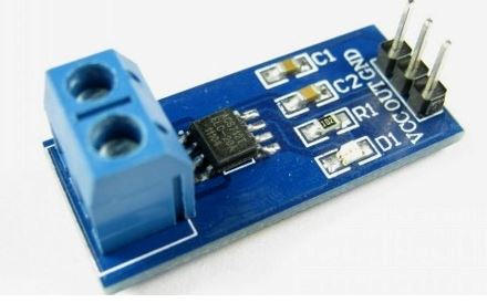
Figure 3 - The appearance of the current sensor on the Hall effect
Conclusion
It is planned to create a laboratory stand for DC electric drive, where instead of six pulses of transistor control will be used only 4.Thematics of the development of the algorithm was begun in the baccalaureate. At the time of writing this abstract, master's work is not completed yet. Estimated completion date of master's work: June 2018. Full text of the work and materials on the topic can be obtained from the author or his manager after the specified date.
References
- Анучин, А.С. Системы управления электроприводов: Учебник для вузов/ А.С. Анучин.- Москва: Издательский дом МЭИ, 2015.-373с.
- Использование датчика тока ACS712. Часть 1 - Теория // rlocman.ru – Режим доступа: rlocman.ru, свободный.
- Обзор применений Plug N DriveTM //Plug'n Drive – Режим доступа: plug_n_drive, свободный.
- Обзор микроконтроллеров семейства STM32F4 //STMicroelectronics – Режим доступа: STM32F4, свободный.
- Шавелкин, А. А. Преобразовательная техника Шавьолкін, О.О. Перетворювальна техніка: учеб. пособие/ А.А. Шавелкин [и др.]. – Краматорск: Донбасская ДМА, 2008. – 328 с.
- Зиновьев, Г. С. Силовая электроника : учебное пособие для бакалавров [Электронный ресурс]/ Г. С. Зиновьев. – 5-е изд, испр и доп. –Москва : Издательство Юрайт, 2012. – 667 с. – Режим доступа: silovaya electronica, свободный.