
Abstract
Content
- Introduction
- Theme urgency
- Launchers of existing ATS devices
- Launchers of existing fast–acting ATS devices
- Conclusion
- References
Introduction
Powerful electric motors 0.4 and 6 (10) kV are used in the systems of auxiliary needs of nuclear and thermal power stations, chemical, metallurgical, oil and gas production and processing enterprises, water supply and water disposal enterprises as drives for compressors, pumps, fans, conveyors, mills, crushers, etc.
Uninterrupted operation of the main mechanisms involved in the continuous technological process in the above-mentioned enterprises is possible only under condition of their reliable power supply. In order to solve the issue of reliability of power supply, the electric power supply scheme of an industrial enterprise must be built in such a way as to ensure the successful operation of means to preserve the uninterrupted operation of the technological process and the functioning of all the main mechanisms in the post- fault regime. Therefore, for enterprises with a continuous process, power must be provided from two mutually reserved independent power supplies (Fig. 1). As a backup power source, local power stations, power stations of power systems, storage batteries, special uninterruptible power supplies, and also power from two sections or bus systems of one substation can be used.
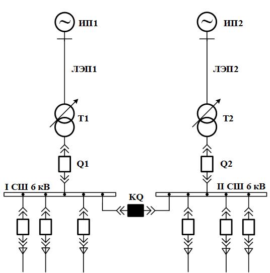
Figure 1 – Scheme of power supply of an industrial enterprise
Theme urgency
The power failures that occur in the power supply system are manifold in duration and in the depth of the voltage drop at the terminals of the motors. Practically any kinds of power failures lead to a change in the operating modes of electric motors and can lead to their loss of stability, if, due to a power failure, a significant change in the performance of the electric drive has occurred.
The most effective means to improve the reliability of the power supply of an enterprise for short-term violations in the power supply system is the application of automatic transfer switching (ATS) and subsequent self-starting of electric motors after the operation of the ATS devices.
Launchers of existing ATS devices
The principle of operation of ATS devices in distribution substations without the motor load is well known and is based on the application of under voltage launchers [1] or the so-called "fast" ATS, when the sectional switch is switched on immediately after the circuit breaker of the section has been switched off accidentally or disconnected from the protection of the supply transformer[2].
If the motor load is present in the electric power supply scheme (Fig. 2), the time of the ATS device operation can be delayed, since synchronous motors in the event of power loss by one section go into the generator mode and rotate by inertia for 3-8 seconds maintain a sufficiently high voltage level on the section and in this case the starting element of the minimum voltage does not immediately work and during the cycle of the automatic transfer system the motors fall out of synchronism with respect to the reserve power supply, which subsequently leads to their non-synchronous switching on. To prevent non-synchronous activation of the motors in the backup power supply circuit, it is also necessary to introduce a control of the reduction of the residual voltage on the section that has lost power below 0.25 - 0.4 of the nominal voltage [3].
Figure 2 – Switching to backup power source
Known method of ATS for substations, with synchronous motors [4], based on the measurement of the integral value of the difference between the actually consumed active power and the power necessary for the stable operation of the motors in the event of violations of the normal power supply mode. Switching to the backup source in this method occurs in the event of exceeding the set value obtained by the value of the integral difference. The disadvantage of this method is the low speed due to the need to determine over a long time interval of actually consumed active power [5].
Also known is the scheme of the ATS device [6], wherein in order to increase reliability and stability of electric motors, in series with the normal section switch is set enabled quick switching device, closing off the network before the damage in the feed accession. However, a significant drawback of this scheme is that motors that do not lose power a short time connect to the schort-circuit, and all synchronous motors of the substation can briefly lose their excitement, since the voltage at the input of exitation coil connected to the substation buses will be close to zero.
Loss of power at the working input can be detected by a deviation from the normal values of various parameters of the regime, and the use of the section voltage as a controlled parameter is not effective, since in the case of power loss, it remains sufficiently long at the level corresponding to the nominal value. Therefore, to improve the performance of AVR devices in power supply schemes with motor load, the schemes of the combined launching are widely used.
Since in the case of power loss, the frequency on the section decreases significantly faster than the voltage, then to accelerate the restoration of power, the ATS device [7] launcher mechanism of the minimum voltage of which is supplemented by a launcher that reacts to a decrease in frequency and control of the normal frequency on the reserve source.
Known ATS device [8], in which launcher of the minimum voltage is supplemented by a launcher that reacts to the angle between the voltage vectors of the main and reserve power sources. Studies show that when using such a launcher, the fact of power loss can be detected faster than when using a launcher that reacts to a reduction in the frequency of the voltage maintained by synchronous motors. The control of the angle value makes it possible to evaluate the possibility of supplying backup power based on the condition of admissibility of currents and moments.
Methods of ATS [8, 9] the launchers of which reacts to the angle between the voltage vectors of the main and backup power sources and to the direction of the active power at the input of the main power source, it is possible to detect the fact of the loss of power during the time 0.2 - 0.4 sec. The disadvantages of this approach include the impossibility of detecting asymmetrical short circuits in the power circuit, since in these modes the direction of active power at the input of the section does not change [10], as well as an increase in the response time due to the conservation of the direction of active power at the input due to its flow between the motors with different time constants.
ATS method [11] in order to increase the speed and exclude unnecessary starting, in addition to measuring the angle between the voltage of the main and backup source, it includes measuring the rate of decrease of the frequency of the main source. However, the supply of backup power is done without monitoring the magnitude of the angle between the voltage vectors of the main and backup power sources at the moment of switching on the backup power, which does not allow the use of such a method of ATS for high-power electric motors.
Also known is the launching of the ATS [12], which responds to a sequence of pulses corresponding to the positive and negative half-wave sinusoidal voltages of the primary and backup power supply.The fixation of power loss in this approach is carried out by a sequence of pulses that correspond to the normal mode and emergency modes. The disadvantage of this approach is the complication of the logical part of the launcher arm of the ATS that performs the analysis of the sequence of pulses in order to detect power loss.
The considered ATS devices do not provide uninterrupted power supply of substations with synchronous and asynchronous motors, since the action of the AVR devices after the voltage failure can reach several seconds. Such a delay in the operation time of the ATS devices can lead to the occurrence of hydraulic shocks, the disconnection of frequency-controlled drives, the overturning of asynchronous and synchronous motors out of sync, the fallout of contactors and magnetic starters with a voltage of 0.4 kV [13].
Launchers of existing fast - acting ATS devices
To improve the reliability of power supply and to ensure the dynamic stability of the motor load during short-term power failures, the distribution of fast-acting automatic transfer switch (FATS) devices, which allow almost instantaneous switching to a backup power source and do not require the removal of excitation from synchronous motors.
System of fast switching to a backup power source [14], includes a FATS device that, in combination with high-speed switches, provides switching times in the range up to 100 msec. The device constantly compares the voltage at the main source with the voltage of the backup power source, and also monitors the voltage amplitudes, the frequency difference and the phase angle between the main and backup power supplies to provide synchronization conditions [15]. The device has four power switching modes [16]: fast switching, switching at the first phase coincidence, switching over residual voltage, switching with time delay. The disadvantage of this system is that the device BAVR controls only the voltage of each section, and it, with close short circuits, can be significantly distorted [17], which can lead to wrong operation of the FATS device, as well as the need for high-speed protection to activate the FATS device.
Known method of FATS [7], which includes measurement of the main and backup power supply voltage of the direct sequence voltage, the angle between the direct sequence voltage vectors, the minimum input current of each section, and the determination of the active power direction at the input of the main power bus. Switching to the backup source occurs when the voltage across the bus bars of the main power source drops below a specified level, or when the angle between the direct sequence voltage vector exceeds a predetermined level and when the active power is transferred from the bus to the main power source. In addition, the minimum input current of each section is measured by comparing it with the set input current value, and when the preset current is exceeded, the switching to the standby power source is also performed. The blocking signal for the operation of the FATS is the direction of the power of the direct sequence [18]. However, such a method has a low response time because the response to an emergency mode is determined by calculating the input power based on voltages and direct sequence currents that, for asymmetrical short circuits, can not change direction.
FATS device for substations with motor load [19] includes the measurement on the busbars of two inputs of phase currents and voltages and their transformation into currents and voltages of direct sequence. This method of FATS includes two ways of starting: voltage starting and corner starting. Both methods are complemented by a direct sequence power directional control by calculating the angle between the forward sequence current of the main power source and the vector sum of the direct sequence voltage of the main power source and the ratio of the direct sequence voltage of the reserve power supply taken as 0 to 50%. The operation of FATS is blocked when the directional power of the direct sequence changes. For modes with low input currents, when the operation of the direct sequence power directional unit is not predictable, a minimum current monitoring is provided. The disadvantage of this approach is the impossibility of correctly determining the direction of the power of the direct sequence in single-phase, two-phase and two-phase to ground short circuits, since the direction of active power at the substation inputs does not change in the consumers' supply circuit and its consumption continues with the motor load.
The principle of FATS described in [20] is to measure the instantaneous values of the line voltages on the buses of the main and backup power sources and to measure the instantaneous values of the phase currents at the input of the main power source, the further transformation of the instantaneous values of voltages and currents into effective values of voltages and currents. Also, the complex effective values of the voltages are converted into complex acting values of the direct sequence voltage of the primary and backup power supplies. The FATS starting device is equipped with a phase-by-phase control of the current direction at the input of the section by measuring the values of the angle between the vector of the complex acting current in phase and the vector sum of the complex acting voltage between the two other phases on the buses of the main power source and taken equal to from 0 to 50% of the fraction of the same complex acting voltage on the bus of a back-up power source. The disadvantage of this method is the unreliability of operation in the case of phase-to-phase short circuits in the mains supply, since in this case one of the line voltages on the main power supply section will be zero and the device will not work [21].
FATS method [21] includes the measurement on the buses of the primary and backup power supplies of the direct sequence voltage and the calculation of the angle between the direct sequence voltage vectors. The launcher of FATS monitors the direction of power, determined on the basis of phase currents and opposite linear voltages, taking into account the maximum sensitivity angle, and in the case where the values of the line voltages on the bus bars of the main source are less than the set voltage value, the voltage of the backup section. The minimum input current of each section is also measured. A disadvantage of this method is the need to perform a large number of measurements to determine the direction of power in each phase of the main and backup power sources.
To ensure a higher level of performance of ATS devices in the works [22-24] В качестве коммутационных устройств предлагается использовать бесконтактные тиристорные коммутационные устройства. Такие устройства называются тиристорами ATS (TATS). The thyristor switch in the TAVR devices is designed for the fastest switching on of the backup power supply up to the moment of switching on the sectional switch and is a three-phase contactless switchgear connected in parallel to the sectional switch [24]. The speed of the TWA devices is affected by their control system and network parameters [25]. So, for example, based on the condition of the permissible error angle between the main and backup power supply voltages, the highest performance of TWA devices will occur in the case when the main power source is in the phase of voltage ahead of the reserve one. However, the presence of a phase shift between the two sources will not allow the main and backup power supplies to be switched to parallel operation, and the phase shift between power supplies in existing substations is difficult to implement.
Conclusion
From the above review of literary sources it follows that the devices of fast-acting ATS are gaining in popularity in recent years and many firms continue their further development. However, most manufacturers of such devices do not disclose the principles of the construction of fast-acting ATS launching organs.
References
- Левченко М.Т., Хомяков М.Н. Автоматическое включение резерва, - М.: Энергия, 1971. – 80 с.
- Беляев А.В. Противоаварийное управление в узлах нагрузки с синхронными электродвигателями большой мощности, - М.: Энергопресс, 2004. – 80 с.
- Шабад М.А. Релейная защита и автоматика на электроподстанциях, питающих синхронные двигатели. – Л.: Энергоатомиздат, 1984. – 64 с.
- А. с. 1262627 СССР, МКИ Н 02 J 9/00. Способ включения резервного питания потребителей / Кузнецов В. Г., Ландман А. К., Пасынков Ю. А. Опубл. в Б.И. 1986,. № 37
- Патент на изобретение 2326481(13) C1, Российская федерация, МПК H02J 9/06 Способ автоматического включения резервного электропитания потребителей и устройство для его осуществления / Цырук С.А., Гамазин С.И., Пупин В.М., Козлов В.Н., Павлов А.О.; заявитель и правообладатель Государственное образовательное учреждение высшего профессионального образования "Московский энергетический институт (технический университет)" (ГОУВПО"МЭИ(ТУ)"). - № 2006139086/09; заявка 07.11.2006; опубл. 07.11.2006
- А.с. 505083 СССР, МКИ Н 02 J3/00. Устройство для энергоснабжения потребителей / Галицын А.А.; Горьк. отд. Энергосетьпроект. № 1466266; Заявл. 07.09.70; Опубл. в БИ, 1976, № 8.
- А.с. 693508 СССР, МКИ Н 02 J 9/06. Устройство для автоматического ввода резерва питания потребителей / Разгильдеев Г.И., Носов К.Б., Брагинский В.И. и др.; Кемеровский технолог, ин-т пищевой пром-ти. №2526208; Заявл. 16.09.77; Опубл. в БИ, 1979, № 39.
- А. с. 1046844. Устройство для автоматического включения резервного питания потребителей /Стальная М.И., Банкин С.А., Богатырев JIJI., Шевляков Э.Ф. Опубл. в Б.И. 1983, № 37.
- А. с. 493858 Устройство для автоматического управления секционными выкл1очателями при самозапуске / Чебан В. М., Удалов С. Н. Опубл. в Б.И. 1979, № 47.
- Патент на изобретение 2398338 (13) С1, Российская федерация, МПК H02J 9/06 Способ автоматического включения резервного электропитания потребителей (варианты) и устройство для его осуществления / Жуков В. А., Пупин В.М., заявитель и правообладатель Жуков В. А., Пупин В.М.. - №2009130901; заявка 30.04.2009; опубл. 27.08.2010.
- А. с. 708463 Способ автоматического включения резрвного пиатния потребителей / Фишман В.С., Никешин B.К., Квашенников В. А. Опубл. в Б.И.1980, №1
- Бороденко В. А., Поляков В. Е. Пусковой орган ввода автоматического резерва для комплексной нагрузки // Электричество. 1982 №5. С. 13 – 18.
- Никулов И. Комплекс БАВР Быстродействие повышает надёжность электроснабжения / И. Никулов, В. Жуков, В. Пупин // Новости электротехники. – 2012. - №4. – С. 2 – 4
- 30 ms High Speed Transfer System (HSTS): Product Description [Электронный ресурс] / ABB Power and productivity for a better world, - 2011, - 12 с. – Режим доступа: http://www.abb.ru/.
- SUE3000 High Speed Transfer Device: Product Description [Электронный ресурс] / ABB Power and productivity for a better world, - 2010, - 24 с. – Режим доступа:http://www.abb.ru/.
- High Speed Transfer Device and System SUE 3000 [Электронный ресурс] / ABB Power and productivity for a better world, - 2010, - 49 с. – Режим доступа:http://www.abb.ru/.
- Баширов М.Г., Кузнецов А.С., Саблин С.А. Анализ параметров и характеристик при выборе устройств быстродействующего автоматического ввода резерва (БАВР) для систем электроснабжения предприятий нефтегазовой отрасли // Нефтегазовое дело: электронный научный журнал . - №4. – 2013.
- Э. Киреева, В. Пупин, Д. Гумиров Современные устройства быстродействующего АВР // Главный энергетик. - №11. – 2005. С. 23 – 26.
- Жуков В. А. Повышение эффективности работы быстродействующего АВР для подстанций с электродвигательной нагрузкой: дис. кандидата технических наук: 05.09.03 / Жуков Владимир Анатольевич. – М., 2008. – 165 с.
- Гумиров Д.Т. Оценка виляния кратковременных нарушений электроснабжения на работу потребителей нефтедобывающих предприятий и разработка устройства АВР для надежного их электропитания: дис. кандидата технических наук: 05.09.03 / Гумиров Дамир Тахирович. – М., 2010. – 206 с.
- Патент на изобретение 2447565(13) С1, Российская федерация, МПК H02J 9/06 Способ автоматического включения резервного электропитания потребителей и устройство для его осуществления / Гамазин С.И., Жуков В. А., Куликов А.И., Пупин В.М., Цырук С.А.; заявитель и правообладатель Федеральное государственное бюджетное образовательное учреждение высшего профессионального образования "Национальный исследовательский университет "МЭИ" (ФГБОУ ВПО "НИУ МЭИ"). - № 2011105886/07; заявка 17.02.2011; опубл. 17.02.2011.
- B. Tian, C. Mao, J. Lu et al., “400 V/1000 kVA hybrid automatic transfer switch,” IEEE Transactions on Industrial Electronics, vol. 60, no. 12, pp. 5422–5435, 2013
- H. Mokhtari, S.B. Dewan, M.R. Iravani, Performance Evaluation of Thyristor Based Static Transfer Switch, IEEE Transactions on Power Delivery, Volume: 15, July 2000, pp. 960-966.
- Tarlochan S. Sidhu, Vinayagam Balamourougan, Manish Thakur, and Bogdan Kasztenny " A Modern Automatic Bus Transfer Scheme", International Journal of Control, Automation, and Systems, vol. 3, no. 2 (special edition), pp. 376-385, June 2005.
- A. Sannio, Static Transfer Switch: Analysis of Switching Conditions and Actual Transfer Time, IEEE Power Engineering Society Winter Meeting, Columbus, Ohio, 2001.