
Abstract
Content
- Introduction
- 1. Formulation of the problem
- 2. Material and methods
- 3. Results and its discussion
- Conclusions
- References
Introduction
Designing power supply systems for consumers is a specific task of engineering creativity. The designer does not need to design a new electrical product, but the ability to create a complete system that meets the specified requirements from prefabricated electrical devices (transformers, starting and protective equipment, cables, wires, etc.) [ 4 ], [ 5 ], [ 7 – 10 ]. The complexity of the design of power supply systems is characterized, first of all, by the incomplete information at all stages of development and by the multicriteria nature of the initial requirements. The projected system should meet both the requirements of regulatory documents and the economic and operational requirements for it by various stakeholders [ 3 ], which have characteristic interests and different points of view on the system , which are expressed in their different representations about the system being designed. Therefore, the high level of uncertainty accompanying the creation of the power supply system throughout the design process (from the analysis of the technical assignment to the development of the design documentation) does not allow to apply fully the exact mathematical methods for solving the problems of automated design of the power supply system. Thus, the basic approach to the design of power supply systems for agricultural consumers is the subjective knowledge and experience of the designer, which is always characterized by incompleteness and fragmentation, which affects the quality of the projected system.
1. Formulation of the problem
Currently, there is no software package that provides support for consumer power supply systems throughout their life cycle. It is prudent to develop a PLM-system that allows integrating CAD systems of power supply systems and assessing the economic component of the adopted design decisions.
2. Material and methods
The purpose of the work : One of the directions of changing existing approaches to the design of power supply systems is the use of methods of system engineering [ 3 ], [ 6 ], because system engineering is an interdisciplinary approach and the way to implement a successful system of any nature.
The most important stage in the process of designing the power supply system is the stage of developing the requirements for the system, that is, describing it as a "black box" that takes into account the requirement of all interested parties. Usually this is either a specification, that is, an exact formulation of a parameter, or a condition that must or can be satisfied, or a function that must be performed, or a characteristic that needs to be achieved. So, for example, the requirement of a minimum cost of the power supply system imposes its demands on the architecture of the system (a minimum of equipment, lower quality, a reduction in the length of cables and wires, etc.).
The success of the development of the power supply system is enhanced by the use of computer-aided design (CAD) systems. To manage the life cycle of technical systems, PLM (product lifecycle management) software is used, which is an integrator connecting various local CAD systems (computeraided design) [ 2 ] . The information about the object contained in the PLM-system is a digital mockup of this object. The advantage of PLM-system is that it provides management of all information about the object and related processes throughout its life cycle, from design and manufacturing to liquidation. Unfortunately, such a software product for the needs of designing power supply has not yet been developed.
For the development of power supply systems, including agricultural consumers, CAD systems of various firms are used, having their own forms of data representation and functional properties and performing a relatively small number of tasks in the design of power supply systems. Among the most common and promising are the following:
-Siemens SIMARIS design;
-nanoCAD Electro firm Nanasoft;
-program products of the CSoft group of companies.
3. Results and its discussion
SIMARIS design is a software package for the development of power distribution systems for industrial, residential and non-residential buildings [ 2 ], these are innovative software tools that represent reference solutions for the design of distribution and internal electric networks. This software package includes design, configuration and support tools, support and interface tools. The SIMARIS design package provides construction of a computational single-line scheme of the power supply system and automatic selection of start-protection equipment ensuring full selectivity of protection and compliance with the regulatory requirements for electricity [ 1 ]. The main drawback of this software product is that only equipment manufactured by Siemens is selected.
The software product nanoCAD Electro can be used for the design of power electrical equipment, indoor and outdoor artificial lighting for industrial and civil buildings. The functionality of nanoCAD Electro allows the design engineer to perform only the solution of conceptual issues, freeing him from routine work: marking equipment, cumbersome calculations, determining the need for equipment, materials, purchased products and information in the specification, maintaining the cable log, forming circuit diagrams of the electrical network . At the same time, the risk of errors in the design documentation caused by the "human factor" is minimal. Using the software product nanoCAD Electro ensures the improvement of the quality of projects and developer productivity.
The own graphics core makes nanoCAD Electronically independent CAD, independent of graphics programs. The electronic support for DWG format (from drawing - a binary file format used for storing 2D and 3D project data and metadata) in nanoCAD provides an unobstructed exchange of information with other developers (subcontractors) and customers. The software product nanoCAD Electro solves such basic problems of designing of systems of electrosupply, as calculation of illumination and arrangement of illuminating devices in premises; the placement of power electrical equipment; tracing and laying of cable lines; determination of the settings of protective devices and cable sections; design of project documentation.
Advantages of nanoCAD Electro:
- own graphics core;
- A clear interface;
- the built-in Project Manager
;
- a wide range of different settings, allowing you to organize design work in full accordance with the standards of the organization and the features of the projects being developed;
- the ability to automatically mark equipment and cables with a custom mask, as well as manually fill in the technical task and import it from the XML exchange file (eXtensible markup language);
- development of electrical network options on several plans and maintaining links between them;
- simulation of the power and control electrical network;
- the presence of applications such as Check Wizard
(controls the quality of the electrical network, the choice of equipment and cables) and Database Manager
(manages data in the system databases) .
Briefly analyze the process of developing the power supply system in the program nanoCAD Electro. By means of special tools, the developer creates a model of the project, makes a plan for the arrangement of equipment and laying of cable lines. The program nanoCAD Electro automatically implements all necessary calculations, the developer selects the cable cross-sections and the settings of the protective devices, and the program checks. After this, all project documentation (except for the plan) is automatically generated.
The work in nanoCAD Electro begins with the opening of the The model of the electric network is created by drawing up a plan for the location of equipment and laying cable lines on a previously created architectural base. By means of special tools, the developer arranges equipment on the plan, "connects" electric receivers to switchgears, runs cable lines. After this, the plan is finalized. Commands Project Manager
window, which contains the tools for managing the documents of the project being developed (creation, deletion, connection, preview, editing, etc.), as well as equipment databases. The project manager ensures the storage of project documents and quick access to them. In nanoCAD Electrode, you use database partitioning on the project database and application databases, which can be many, they can be generated by manufacturers and types of equipment. The necessary equipment is freely moved from the application databases to the project database, the specified procedure is performed by the Database Manager .
Attributes
, Callout
and Special. callout
allow you to put callouts to equipment, cable lines, rooms.
(3.1)
An essential disadvantage of nanoCAD Electro is that the choice of the types and settings of the starter protection equipment is carried out by the designer on the basis of the calculation of the electrical model, which can lead to a violation of the selectivity of the protection of the power supply system elements [ 1 ].
CSoft group of companies develops and delivers CAD software that allows to realize the whole technological chain of designing of electrical part for production facilities, including for such specific ones as power supply systems of auxiliary needs of thermal and nuclear power stations [ 2 ]. The main software modules are the following products.
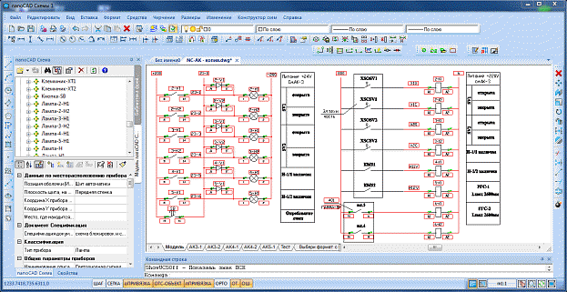
AutomatiCS program automates the design of control and management systems, electricity metering. AutomatiCS is a multi-user CAD system that supports all stages of design work from obtaining a technical task for the development of an automated control system to a design solution and documentation. The use of AutomatiCS in the practice of design works ensures the improvement of the quality of projects, the reduction of the time for the execution of design work and the reduction in the number of errors in the design documentation. AutomatiCS implemented the reuse of data already developed projects. Simultaneous work of several developers with one project is supported, which is facilitated by multi-user access to project data, as well as to a database of technical facilities and standard project solutions.
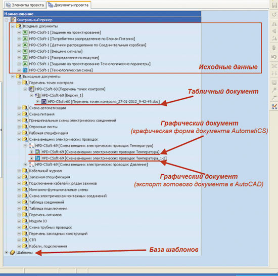 |
(3.2) |
The software package ElectriCS 3D is used for automated routing of cables for various purposes in buildings and on open areas. The original technologies of ElectriCS 3D allow to ensure the quality of project documentation by reducing the number of errors that are unavoidable in manual design; reduction of cable and protective tube consumption; increasing the productivity of designers; reduction of the terms of design and costs for the construction and operation of utilities.
- single-line diagrams of internal and distribution electrical networks in the traditional vertical (graphical) representation, as well as in horizontal (tabular);
- common types of electrical panels; lists of components to them;
- custom specifications of equipment, materials, products;
- load matrices, voltage losses, short-circuit currents;
- cable logs.
 |
(3.3) |
ElectriCS Light performs lighting calculations and is used in the development of electric lighting systems for enterprises. ElectriCS Light allows the calculation of indoor lighting and outdoor lighting of production sites. The essential advantages of the ElectriCS Light package, which distinguishes it from similar CAD systems, are:
- calculation of illumination using curves of luminous intensity (with tracking of shadows and reflections);
- the possibility of obtaining a composite result in the calculation of multiple rooms, viewing in the three-dimensional image the results of calculating the light fields, which enables the developer to estimate the distribution of illumination over the area of the illuminated territory; receiving ready-made project documentation in AutoCAD and Microsoft Word formats.
Software package EnergyCS Electricity - the system of electrical calculations for the design of internal and distribution electrical networks, it combines a convenient interface and a comprehensive approach for calculating the modes of open internal and distribution networks. EnergyCS Electricity is used to design internal electrical networks of various enterprises, distribution networks, power supply systems for auxiliary needs of power plants and substations, to develop technical conditions for connecting new consumers to power sources, as well as for operational monitoring and analysis of possible modes of electrical networks.
The main disadvantage of all listed systems of power supply systems is that they do not allow to determine one of the main indicators of the projected electricity supply system, namely, its cost indicators.
Conclusions
1. For the development of power supply systems, including agricultural consumers, CAD systems of various firms are used, having their own forms of data representation and functional properties and performing a relatively small number of tasks in the design of power supply systems.
2. At present, there is no software package that provides support for power supply systems for agricultural consumers throughout their life cycle.
3.Technical is the development of PLM-system, which allows to integrate CAD systems of power supply and to assess the economic component of the adopted design solutions.
References
- Андреев В.А. Релейная защита и автоматика систем электроснабжения : учебник для вузов / В.А. Андреев. – 4-е изд., перераб. и доп. – Москва : Высшая школа, 2006. – 639 с.
- Афоничев Д.Н. Информационные технологии в науке и производстве : учеб. пособие / Д.Н. Афоничев, С.Н. Пиляев, И.И. Аксенов. – Воронеж : Воронежский ГАУ, 2015. – 140 с. [Электронный ресурс]. – Режим доступа (из интрасети ВГАУ): –
- Батоврин В.К. Стандарты системной инженерии: серия докладов (зеленых книг) в рамках проекта «Промышленный и технологический форсайт Российской Федерации» / В.К. Батоврин; под ред. М.С. Липецкой, К.А. Ивановой. – Санкт-Петербург : Фонд «Центр стратегических разработок «Северо-Запад». – 2012. – Вып. 4. – 64 с.
- Герасименко А.А. Передача и распределение электроэнергии / А.А. Герасименко, В.Т. Федин. – Ростов-на-Дону : Феникс, 2008. – 715 с.
- Коробов Г.В. Электроснабжение. Курсовое проектирование : учеб. пособие / Г.В. Коробов, В.В. Картавцев, Н.А. Черемисинова. – 3-е изд., испр. – Санкт-Петербург : Лань, 2014. – 192 с.
- Левенчук А.И. Системноинженерное мышление : учебник / А.И. Левенчук. – Москва : Изд-во МФТИ, 2015. – 305 с.
- Лещинская Т.Б. Электроснабжение сельского хозяйства : учебник / Т.Б. Лещинская, И.В. Наумов. – Москва : БИБКОМ, ТРАНСЛОГ, 2015. – 656 с.
- Фадеева Г.А. Проектирование распределительных электрических сетей : учеб. пособие / Г.А. Фадеева, В.Т. Федин; под общ. ред. В.Т. Фелина. – Минск : Вышэйшая школа, 2009. – 365 с.
- Фролов Ю.М. Основы электроснабжения : учеб. пособие / Ю.М. Фролов, В.П. Шелякин. – СанктПетербург : Лань, 2012. – 432 с.
- Черемисинова Н.А. Проектирование систем электрификации / Н.А. Черемисинова, Д.Н. Афоничев. – Воронеж: Воронежский ГАУ, 2015. – 150 с.