
Abstract
Content
- Introduction
- 1. Theme urgency
- 2. Goal and tasks of the research
- 3. Use of communication protocols for remote control of the electric drive
- Conclusion
- References
Introduction
The Inter-Integrated Circuit bus (or I2C) was developed in the early eighties by the Philips company for intermicrocircuit control in units of TV sets to increase possibilities of television receivers with simultaneous abbreviation of number printing conductors on boards, which connect among themselves all growing integrated chips number [1]. The task of appearance I2C bus was transfer from the parallel communication of data, which inevitably have number of conductors equal to digit capacity of the bus, that considerably complicated distributing of printed circuit boards and created many other problems, to serial data transfer on three wires. Interest at developers and different designers of radio-electronic devices in the I2C bus did not weaken all these years, but canceling since October 1, 2006 by the Philips company of assignments for use of the I2C protocol caused revitalizing of interest and gave a new impetus to more and more wide use of the I2C bus in different electronic devices, which are not connected to television reception. It is a lot of years engineers and developers by development and debugging of the devices using the I2C protocol applied software and hardware tools, if allowing to make decoding of the I2C protocol, then absolutely not fitted to the analysis of these signals at the physical layer, that is with visual viewing of the processes happening on the bus with simultaneous decoding of the I2C protocols. These problems are completely solved by the modern digital oscillograph having a possibility of decoding I2C protocols. It is possible to carry oscillographs of LeCroy of the WaveSurfer Xs, WaveRunner, WavePro and WaveMaster series to number of such oscillographs.
1. Theme urgency
Now more and more relevant is a question of remote control to electric drives in connection with impossibility of installation of the control device in close proximity to the working mechanism. At the same time a force part is tried to be located closer to the drive, and to transfer the controlling signals to it far off. In the systems of small automation and mechanisms controlled from inexpensive controllers, for example, with architecture of AVR or ARM, protocols of RS232, SPI and I2C communication are used. Therefore the master's work will be devoted to communication SPI and I2C protocols.
Now the I2C bus is often used in memory chips, video processors, modules of processing audio-and video signals, ADC and DAC, LCD drivers of indicators and also in phones, codecs and in other devices. Vendors of digital oscillographs also used the I2C interface.
2. Goal and tasks of the research
Research objective to check operation of the communication I2C protocol, to receive results of researches and to draw conclusions, proceeding from results of a research.
Main objectives of a research:
- To connect L3G4200D gyroscope to STM32F4 Discovery board, using the communication I2C protocol.
- To trace signals of two bidirectional communication lines (SDA and SCL) by means oscillograph.
- To receive results of operation I2C protocol (diagrams of communication lines SDA and SCL) and results of operation gyroscope L3G4200D.
- To draw conclusions on results of operation I2C protocol.
Object of a research is the sensor L3G4200D which transfers data to STM32F4 Discovery board according to the communication I2C protocol.
Within the master's work it is planned to receive relevant scientific results on operation of SPI and I2C communication protocols for remote control of the electric drive and also to compare them.
3. Use of communication protocols for remote control of the electric drive
I2C bus is one of modifications of serial exchange protocols data [2]. In a standard mode transmission of serial 8-bit data with speed up to 100 kbps, and up to 400 kbps in the fast
mode is provided. For implementation of process information exchange on I2C bus, only two signals are used: line of the data SDA (line of synchronization) and SCL (line of clock periods). The simple two-wire serial I2C bus minimizes the number of connections between devices.
Each device is distinguished to the unique address and can work as the transmitter or the receiver, depending on the appointment.
Besides, devices can be classified as master and slave in case of data transfer. Master is a device, which initiates data transfer and works out synchronization signals. At the same time any addressed device is considered slave in relation to the master.
Proceeding from the specification of operation bus, at each separate moment in the bus there can be only one master, namely that device, which provides formation of a signal SCL bus. The master can act as the master-transmitter, and the master-receiver. Nevertheless the bus allows to have several masters, superimposing certain features of their behavior in formation of signals control and monitoring of bus state. The possibility of connection more than one master to the bus means, that more than one master can try to begin transfer to the same timepoint.
The procedure of exchange begins with the fact that the master forms a state START – the master generates transition of SDA signal line from the HIGH state in LOW at HIGH level on the SCL line.
The procedure of exchange comes to the end with the fact that the master forms a condition of STOP – transition of a condition SDA line of a LOW state in HIGH at the HIGH condition of the SCL line.
For receipt acknowledgment of byte from the master-transmitter carried slave-receiver into specifications of the exchange protocol on the I2C bus enters the special bit of confirmation exposed on the SDA bus after reception of the 8th data bit.
Thus transfer of 8 bits of data from the transmitter to the receiver come to the end with an additional cycle (formation of the 9th clock impulse of the SCL line), at which the receiver exposes the low level of a signal on the SDA line as sign successful reception of byte.
Confirmation in case of data transfer is mandatory. The appropriate pulse of synchronization is generated by the master. The transmitter releases (HIGH) the SDA line for the period of confirmation sync pulse. The receiver shall retain the SDA line during the HIGH state of sync pulse confirmation in a stable LOW state.
If the master-receiver participates in transfer, then he has to report about the end of transfer to slave-transmitter by non-confirmation of the last byte. Slave-transmitter must to free the line of data to allow the master to give a signal STOP or to repeat a signal START.
Each device, connected to the bus, can be programmatically addressed on a unique address.
The procedure of addressing on the I2C bus is that the first byte after a signal defines START, what slave is addressed to masters for carrying out a cycle of exchange. The exception makes the address of the General call
, which addresses all devices on the bus. When this address is used, all devices shall send an acknowledgement signal to theories. However, devices, which can process the general call
, in practice meet seldom.
The first seven bits of the first byte form the address of slave. The eighth, least bit, defines the direction of transfer data. Zero
means, that the master will write information in the chosen slave. Unit
means, that the master will read out information from slave.
After the address is sent, each device in system compares the first seven bits after a signal START to the address. At coincidence the device believes itself chosen as slave-receiver or as slave-transmitter, depending on direction bit.
In a general view process of exchange on the bus from the moment of formation state the START to a state of STOP is shown in a figure 1.
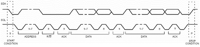
Figure 1 – Process of data exchange on I2C bus
The abbreviation of SPI means Serial Peripheral Interface
or in the Russian option последовательный периферийный интерфейс
[3]. The name speaks for itself, this interface is used for operation with different peripheral devices. From the technical point of view SPI is a synchronous four-wire bus. It represents connection of two synchronous shift registers, which is the central element of any SPI device. For connection the configuration master / slave is used. Only the master can generate synchronization pulses. In the diagram always only one master (unlike the same I2C bus, where the option with more than one master is possible), quantity of slave can be variously. Generally the output of the master connects to an input slave and vice versa, the output of slave connects to the master's input. In case submission of synchronization pulses on SCK output, data are pushed out by master from MOSI output, and are captured by slave on MISO input. Thus, if to give the number of synchronization pulses, appropriated to digit capacity of a shift register, then data in registers will exchange places. From here follows that SPI always works in the full-duplex mode. And whether here we need the data, obtained from the device in case of record any parameter, it is already other question. Often happens, that this received data from the device in case of record data are garbage, in that case they are just ignored, but we will receive them regardless of our desire.
The SPI controller, as a rule, can work both in master's mode, and in the slave's mode.
There is the simplest way of turning on SPI devices. Such way is shown in the figure 2.
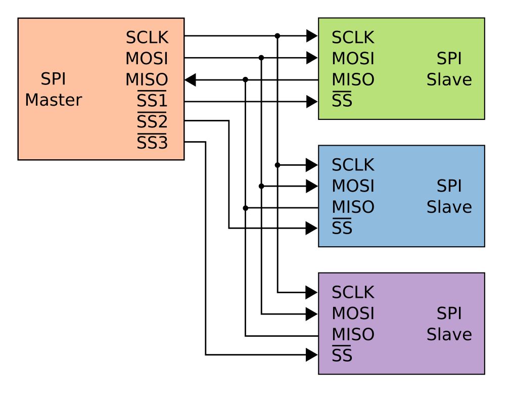
Figure 2 – Way of turning on SPI with parallel connection of the slave devices
In this case all slave's are connected to the master parallely, except for a choice slave signal (by CS). The separate slave select signal (in a figure they are designated as SSx) is necessary for each slave. The dedicated SPI controller outputs and the general-purpose GPIO ports of the microcontroller can be used for slave select signals.
Two conductors are used for data transfer, one for submission clock pulses and on one choice slave signal for each of slave.
- MOSI – Master Output, Slave Input (master's output, slave's input). This signal is intended for serial data transfer from the master to slave. Also SDO, DO, etc. can be called;
- MISO – Master Input, Slave Output (master's input, slave's output). This signal is intended for serial data transfer from slave to the master. SDI, DI, etc. can be called;
- SCK – Serial Clock (a synchronization signal). It is used for synchronization in case of data transfer. Also can have name SCLK, CLK, etc.;
- CS – Chip Select (a chip select). By means this signal there is an activation of a slave device. Usually it is inverse, that is the low level is considered the active. Sometimes it is called by SS (Slave Select, a Russian
выбор ведомого
).
We will give an example of use I2C protocol.
Let one payment of Arduino Due will be a control system (with buttons for control of the electric drive), i.e. the master device. From this master device data will be transferred to the slave, which is the subordinate speed control system of DC-motor. Thus, by means of I2C-communication it is possible to adjust two payments of Arduino Due so, that they shared information on the principle the master payment sends / the slave payment reads out
. The master payment of Arduino Due sends a signal on start-up, braking and a reverse of the engine and also an input signal of intensity adjuster (the set speed), and slave accepts these data.
The scheme connection of the master and the slave Arduino Due payment is submitted in the figure 3. Contacts of SDA and SCL on the master payment Arduino are connected to contacts of SDA and SCL on the slave Arduino. Besides, contacts with ground
(GND) at both payments are connected to each other too. Buttons of management with light indication are connected to the master payment, and engine connected to the slave payment.
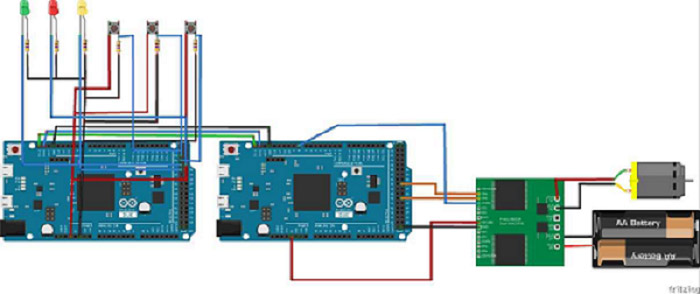
Figure 3 – The scheme of connection master and the slave Arduino Due payment
Conclusion
- The master's work is devoted to a relevant scientific research problem of SPI and I2C communication protocols for remote control of the electric drive.
- Unlike the SPI communication protocol, the I2C bus remains two-wire, irrespective of quantity connected chips to it and is more standardized and also it is possible to connect several master chips to it.
- The SPI protocol is simpler in respect of program implementation and at the physical layer, that causes reliability and high-speed performance of data transfer. All SPI bus lines are unidirectional.
When writing this abstract, the master's work isn't finished yet. Approximate date of end the master's work: June, 2018. The full text of work and materials on a subject can be received at the author or his head after the specified date.
References
- Декодирование и анализ сигналов шин I2C, SPI, RS-232C, RS-422, RS-485 и UART с использованием осциллографов LeCroy // Обработка аналоговых сигналов микроконтроллерами. Выбор и задачи микроконтроллеров. – Режим доступа: http://kursovaya-referat.ru/docs/index-36975.html?page=8
- Описание шины I2C // ООО
ИТТ Лтд
. – Режим доступа: http://itt-ltd.com/reference/ref_i2c.html - Обзор шины SPI и разработка драйвера ведомого SPI устройства для embedded Linux (Часть первая, обзорная) // Хабрахабр. – Режим доступа: https://habrahabr.ru/post/123145/