
Content
- Introduction
- 1. Relevance of the topic
- 2. The purpose and objectives of the study, the planned results
- 3. A Review of Literary Sources
- 3.1 Methods of starting the engine
- 3.2 Series soft starters and soft start systems for belt conveyors
- Conclusions
- List of sources
Introduction
Our region has always been famous for the extraction of minerals, namely the coal industry. An important role in this sector is occupied by transport systems that provide transportation from the coal mining site directly to the processing and storage site for further use as intended. One of the main continuous vehicles in coal mines is a belt conveyor that transports extracted coal from lava, therefore, to it, as well as to all mine systems, high technical requirements are imposed. The wide use of conveyor transport is explained by its advantages over the transport of other types when large volumes of cargo are transported over short distances. Such advantages include: simplicity of design, reliability in work, high productivity and low operating costs. At present, mining in mines is conducted at considerable depth, there is a need to increase the length of conveyor belts, because of this there is a need to consider possible optimal options for smooth starting of the conveyor motor to increase their productivity. This work will be devoted to the study of technical and energy characteristics of a smooth start of the belt conveyor.
1. Relevance of the topic
Ensuring the reliable operation of the belt conveyor, without slipping and jerking, allows to increase the service life of the conveyor parts by reducing the possible deformation of the belt, as a consequence, increases the long-term equipment and optimizes the production of mine resources.
2. The purpose and objectives of the study, the planned results
The aim of the master's work is to study the energy indicators of the smooth start-up of the electric drive of the belt conveyor and to determine effective methods for improving them.
To achieve this goal, it is necessary to solve the following tasks:
- To study the literature on mine conveyor plants and various ways to start the electric drive of a mine belt conveyor, choose the optimal one;
- To develop a mathematical model of a device for smooth start-up of a mine belt conveyor under load, as close to the real object as possible;
- Analyze on the basis of studies on the mathematical model various methods for improving the energy characteristics of the device for smooth start-up of the belt conveyor;
Object of study: Device for smooth starting of mine belt conveyor
Scientists concerned with the application of the soft starter: prof. BA Kuznetsov, Ph.D. V.M. Nazarenko, prof. I.G. Shtokman, prof. L.G. Shaikhmeister, prof. V.G. Dmitriev and many others.
Within the framework of the master's work, it is planned to receive the current scientific resultsin the following areas:
3. A Review of Literary Sources
In this work, an induction motor with a squirrel-cage rotor is used, due to its simple construction and low cost is widespread and has a wide range of advantages. It consists of the following main parts: a stator with a three-phase winding, a rotor with a short-circuited winding. The winding of the rotor is made contactless (it is not connected to any external circuit), which determines the high reliability of such an engine. The work of any asynchronous motor begins with its starting.
3.1 Different ways to start the engine
Direct starting of the electric motor
This type of launch due to its low cost and simplicity is the most common and compact. The design includes a fairly simple circuitry that consists of a linear contactor and a thermal or electronic overload relay. The disadvantage of this method is the increase of the starting current. In the case of direct starting of the conveyor motors, a mechanical shock occurs, which in turn leads to accelerated wear of the equipment (electric motor, reducer, tape, etc.), and a current surge occurs, resulting in a voltage drop in the network. The rated value of the starting current exceeds the value of the motor current by a factor of 6-8, although it operates for a short time. Nevertheless, there are situations when this method is suitable.[1]
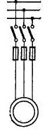
Figure 1 – Direct starting of the electric motor
Start according to the scheme Star – triangle
This starting method is used for motors that are connected in a nominal operating mode by a triangle. At the initial moment of acceleration of the engine, its windings are connected by a star, which provides a reduced current. After a certain time, the connection is changed to a triangle
, which will provide full current and torque. When connected in the "triangle" scheme, the voltage on each motor winding corresponds to the voltage in the network. The motor current is divided between two parallel windings with a factor of 1 / v3 of the total current. If the resistance of each winding of the motor is Z, then the sum of the resistances for the parallel windings is Z / v3. If the motor is connected by a star (Y), its windings are connected in series. The resulting impedance is v3 * Z, as a result of which it will be in (v3 * Z) / (Z / v3) = 3, that is, 3 times higher than the resistance when connected in the triangle
scheme. Since the voltage level is the same, the current for the "star" connection will be 1/3 of the current when connected by a triangle. Therefore, when starting with a star / delta circuit, the current at the star connection is 33% of the motor current connected by a triangle. Since the mains voltage is constant, when the star is connected, the voltage decreases, since the voltage at each motor winding will be 1 / v3 of the line voltage. This reduced voltage will also lead to a reduction in torque. In practice, this value is 25%, since there are additional losses, as well as other features related to the efficiency of the connection in the star
scheme. This starting method is most effective at start-up with no load or with a very lightly loaded start, but when starting the engine under heavy load it is impossible to achieve its nominal speed by switching to a triangle, which often leads to high transient values ??and a large amplitude peak current. In some cases, the peak current may exceed the current value for direct start. In addition, as with direct start, the only way to stop the engine when using the star– delta circuit is to directly stop[1]
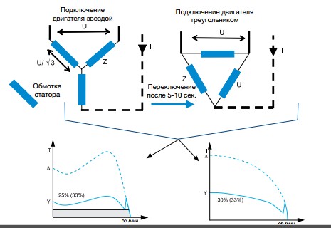
Figure 2 – Start according to the scheme Star – triangle
Frequency converter
The frequency converter is also sometimes called VSD (Variable Speed ??Drive), VFD (variable speed drive) or simply driven. It consists of two main blocks, one of which converts an alternating current (50 or 60 Hz) into a constant one, and the second - converts a constant back into an alternating current, but with a frequency of 0-250 Hz. By controlling the frequency of the current, the drive can adjust the speed of the motor. During start-up, the drive increases the frequency from 0 Hz to the mains frequency (50 or 60 Hz). Due to the gradual increase in frequency, it can be assumed that the motor operates at its rated speed for a given frequency. In addition, since the engine can be considered running at its rated speed, the rated torque is immediately available, and the current will be approximately equal to the rated torque. As a rule, the drive switches off if the current exceeds the rated current by 1.5 times. When using the drive to control the motor, you can also make a smooth stop. This is especially useful when stopping pumps, since it avoids a hydraulic shock, as well as damage to conveyor belts. In many installations, the speed of the motor must be continuously controlled, frequency regulation is very suitable for this. However, in many cases the drive is only used to start and stop the engine, although there is no need for continuous speed control. Such a solution is unnecessarily expensive compared to, for example, a soft starter. When comparing a soft starter and a drive, the latter has much larger physical dimensions and takes up more space. The drive is also much heavier than the soft starter, which makes it a less desirable solution, for example on mobile vehicles, where weight is important. Finally, since the drive changes the frequency and actually creates a sinusoidal wave, when it is used in the network, harmonics will appear. To reduce the impact of these problems, additional filters and shielded cables are used, but harmonics, as a rule, can not be completely eliminated.
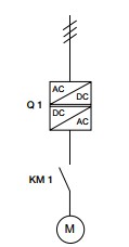
Figure 3 – Frequency converter
Application of the soft starter
The need for relatively inexpensive devices for starting engines with current limitation during overclocking has led to a wide distribution of soft starters (soft starter). The functional circuit of the SCP is essentially a power circuit and the control principle of a converter device known as a thyristor voltage regulator (TPN). Due to the ability to regulate the voltage at the motor terminals, the formation of the current and the motor torque in the starting mode is ensured. SCP, essentially TRH, which introduced a closed system of automatic current control and the device of a parametric (time function) setting the current amplitude. As a result, the soft starter realizes the formation of a specified limited current and the motor torque during the start-up process. The traditional soft start system is selected in the figure to provide a reduction in the starting current at a given level (no more than 2 ... 3 Iн). At the same time, the electrodynamic forces in the windings and the associated mechanical destruction of the insulation of the windings decrease drastically. Reducing the starting times is also beneficial for the mechanical part of the drive. The soft starter does not change the frequency or speed as the drive does. Instead, it gradually increases the voltage that is applied to the engine, from the initial value to the full. Initially, the voltage on the motor at start-up is so small that it is possible to adjust only the gap between the gear wheels or the tensile drive belts, etc., which avoids sudden jerks during start-up. Gradually, the tension and torque increase, and the equipment starts to accelerate. One of the advantages of this starting method is the ability to fine-tune the torque according to needs, and the presence or absence of loading. Using a soft starter allows you to reduce the starting current and thus avoid a drop in voltage in the network. It also reduces the starting torque and mechanical effects on the equipment, which reduces the need for maintenance and repair. Like the drive, the soft starter can perform a smooth stop, eliminating water hammer and pressure jumps in pumping systems and avoiding damage to brittle material on belt conveyors.[2]
To the main parameters of the system, which are set and controlled with the help of Soft Start devices:
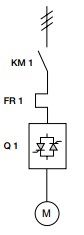
Figure 4 – Soft starter
Reactor starting
This method of starting the engine is to use a three-phase inductive resistance, which allows you to slow down the process of current buildup. The reactor engine is started in this way. Initially, the motor is powered via three-phase, its resistance limits the magnitude of the starting current, so it comes from the network to the stator winding through the reactors, the voltage drop occurs due to the inductive reactance of the reactor on the windings. As a result, a lower voltage is applied to the stator winding. When the normal speed is reached, a switch is turned on, which shunts the reactor, resulting in a normal mains voltage being applied to the motor. More universal is the method with lowering the voltage applied to the motor by means of reactors (reactive coils - throttles).[1]
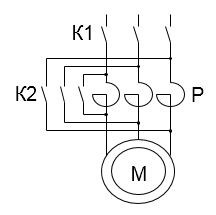
Figure 5 – Reactor starting
Figure 6 – The main characteristics of the reactor start of the electric motor
(animation: 7 frames, infinite repetition cycle, 78.5 kilobytes)
Characteristics
Autotransformer start
Autotransformer start-up, like the previous method, requires a special starting device - an autotransformer, which increases the cost of installation. The transformer ratio of the autotransformer, when starting this way, the starting current in the network and the starting torque of the motor are reduced. In this case, the value of the starting torque, other things being equal, will be greater than during the reactor launch, which is certainly an advantage of the method of starting short-circuited asynchronous motors with an autotransformer. The autotransformer start-up is carried out in the following order. First, an autotransformer is supplied with an undervoltage to the motor stator. In this case, the starting current of an induction motor with a squirrel-cage rotor, measured at the output of the autotransformer, decreases by a factor of K, where K is the transformer ratio of the autotransformer. As for the current at the input of the autotransformer, it decreases by a factor of K2 compared to the starting current when the motor is directly connected to the mains. The fact is that in the decreasing autotransformer the primary current is less than the secondary one in K times and therefore the decrease in the starting current for autotransformer start-up is K2 times[4]
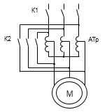
Figure 7 – autotransformer start of the electric motor
Characteristics
3.2 Series soft starters systems for belt conveyors
Altistart 48 series
The soft starter Altistart 48 is a thyristor switching device providing smooth start-up and shutdown of three-phase asynchronous motors with a squirrel-cage rotor from 4 to 1200 kW. It combines the functions of soft start and braking, protection of mechanisms and engines, as well as communication with automation systems. The characteristics of the algorithm for controlling the soft starters Altistart 48 provide high reliability, safety and ease of commissioning.[6]
The main functions of Altistart 48:
Engine and gear protection functions:
Typically, to control one or a group of identical motors with the Altistart 48, you need to connect the controller's digital outputs to the Stop terminals (active signal 0 V) ??and Run (active signal + 24 V). In this case, the "0" power supply of the controller outputs must be combined with the COM terminal of the soft starter. Two more discrete outputs of the controller are used to control the input and bypass contactors. It is possible to control the soft starter and by means of intermediate relays. The relay contacts are used to supply signals to terminals Stop and Run from the terminals + 24V and COM of the soft starter. When designing, it must be remembered that the inputs RUN and STOP are programmed for start and stop commands. The control signals can be constant or pulsed. Two other inputs LI3 and LI4 can be configured to perform certain functions. The list of programmable functions is presented in the catalog on Altistart 48 in the section "Applied functions of digital inputs" .Altistart 48 has two discrete and three relay outputs. The discrete outputs LO1 and LO2 are connected directly to the corresponding inputs of the controller. The list of programmable functions is presented in the catalog on Altistart 48 in the section "Applied functions of digital outputs". The signals from relays R1, R2 and R3 are applied to the corresponding inputs of the controller, with + 24V power supply to the controller inputs to terminals R1C, R2C and R3C, and terminals R1A, R2A and R3A are connected to the controller inputs. When designing, it should be noted that relay R1 can be configured to perform the following functions:
In all cases, when the R1 relay is opened, it is recommended that the controller be programmed to disconnect the mains contactor. The relay R2 is configured only for the bypass contactor function. It closes after the end of the start and opens with the STOP command or with a malfunction. Relay R3 is configured to perform the same functions as the digital outputs LO1 and LO2.Altistart 48 has one analog output AO1. It allows you to send a current signal of 0-20 or 4-20 mA to the analog input of the controller, containing information about the magnitude of the current current or motor torque, engine temperature, active power.[6]
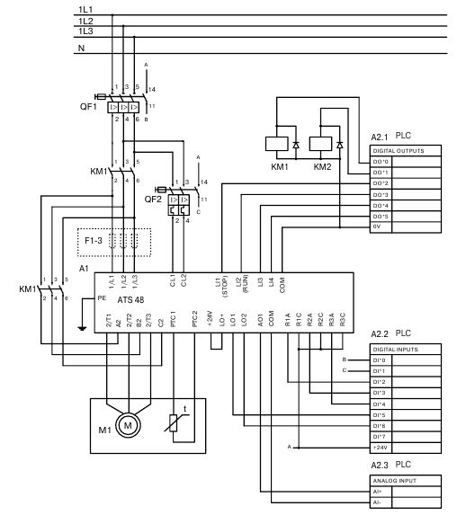
Figure 8 – Control of the Altistart 48 soft starter from the PLC
ABB softstarter type SSM
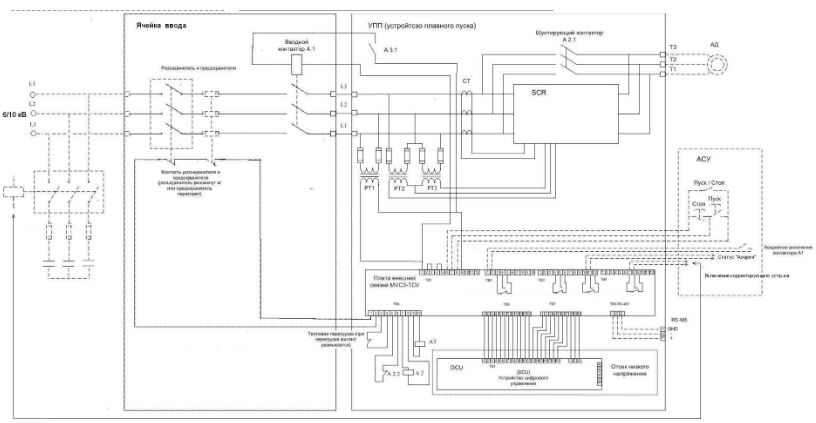
Figure 9 – Schematic diagram of SSM device connections
Conclusions
- A review of the literature on the topic of dissertation work showed that for the optimal operation of the mine belt conveyor it is necessary to use a soft starter.
- The analysis of the soft starter will ensure the elimination of voltage failures when starting the engine, will reduce the starting currents in the switching devices, cable and engine.
- Mining industry especially needs a safe operating mode, the soft starter maximally protects from emergency operation modes (thermal and current protection).
- The solution of the task set in the master's work will provide practical recommendations for the effective use of the soft start device of the mine belt conveyor.
At the time of writing this essay, the master's work is not yet complete. Approximate date of completion of the master's work: June 2018. The full text of the work and materials on the topic can be obtained from the author or his supervisor after the specified date.
List of sources
- Андреев В.П. .Основы электропривода / В.П. Андреев, Сабинин Ю.А// Государственное энергетическое издательство – 1963. –с. 129-153.
- Борисенко В.Ф. Электротехнические системы транспортных механизмов / [Борисенко В.Ф., Чепак А.А., Сидоров В.А., и др.] под ред. Борисенко В.Ф. – Донецк.: НПФ «МИДИЭЛ», 2007. С. 83-89
- Мейстель А. М. и др. Комплектные тиристорные устройства для управления асинхронными электроприводами. -М.: "Энергия", 1971. - с. 27-35.
- Ставицкий В.Н., Маренич К.Н. Полупроводниковый преобразователь для автоматизированного электропривода горной машины. // Наукові праці Донецького національного технічного університету. Серія: обчислювальна техніка та автоматизація. Випуск 58. – Донецьк: ДонНТУ, 2003. – с. 122 – 129
- Техническая коллекция Schneider Electric. Выпуск 26 / Дроздов П.А, Потапов А.В, – М.: Издательский дом «Вильямс», 2009.с.12 –13 .
- Учебное пособие по выбору и применению устройств плавного пуска ABB/: [Электронный ресурс]. – URL: http://www.lanitnord.ru/files/1sfc132060m0201_softstarters_manual_2014.pdf