
Contents
- Introduction
- 1. Relevance of the topic
- 2. Goals and objectives of research
- 3. Review of research and development
- 3.1 Heating system based on skin effect
- 3.2 Heating systems with heating cables
- Conclusion
- References
Introduction
Industrial enterprises, the technology which is associated with explosive energy carriers, according to the PUE, should
have electrical supply for the first special category. Uninterrupted operation of the enterprise in this case depends on the reliability of
the process plant and, therefore, from those processes that occur in it. Therefore, the compliance of
normal conditions
(n.c.) in the context of oil and gas technology is an urgent problem.
In the conditions of permafrost, the negative factor that affects compliance with the parameters of the energy carrier,
obviously is temperature. In gas industry of far North began to be used special technology of electrical heating systems because of their reliability.
[1]
1. Relevance of the topic
Modern oil field, gas field or petrochemical enterprise – it is a complex of process plants, platforms, wells, reservoirs, connected by an extensive network of technological pipelines. Gas or oil Field usually consists of several separate areas, the distance between which can reach 4 to 5 kilometers. There are also various ground-based structure: we are talking about residential and domestic premises, hangars, warehouses, etc. The main objectives of the use of electrical heating systems of the above mentioned objects can be formulated in the following way:
- maintaining the temperature of the transported product (water, oil, petroleum products, natural gas) to 80°C in the fields;
- maintaining the temperature of the transported product over 80°C (fuel oil, bitumen, sulfur);
- preventing deposition of paraffin in oil transportation;
- maintain product temperature (water and aqueous solutions) in the range of 3 to 5°C
- antifreeze;
- heating of backup or auxiliary pipelines with incomplete or non-permanent filling to ensure their operation when necessary;
- heated backing or support pipelines with incomplete or irregular filling to ensure they work when needed;
- the temperature of liquid products during storage in the tank. [2]
The main objects that are subject to electric heating are:
- pipelines for the transport of various products (water, oil, paraffin, sulfur, etc.);
- piping inlet-outlet tank farms and oil terminals;
- pipelines interplant intrashop pipelines and processing;
- pipelines: firefighter, sewer and technological on-site installations of preparation of oil and gas (UCPO, UCPG) and settlements;
- pipelines of water supply (conduits);
- flow lines to a Central collection point of oil (LTP);
- lines and equipment pumping stations;
- tanks intermediate and cumulative storage of liquid products (oil and water reservoirs);
- of the well and downhole equipment on the fields;
- helicopter pads on offshore oil platforms;
- floors open pumping stations pumping oil.
In addition, the electrical heating is used to ensure the normal operation of such facilities as:
- oil gathering manifolds at booster pumping stations (BPS);
- control cabinets and instrumentation;
- nodes of process plants in refineries;
- nodes of compressor stations;
- of the tank and node loading / unloading petroleum products;
- measuring equipment on the pipeline (pressure gauges, counters, and pulse tube);
- pulse measurement lines; [2]
2. Goals and objectives of research
Industrial electric heating Systems are used mainly in the far North. The aim of the study is to collect and organize information, consideration of issues of design of electric heat tracing systems in explosion areas, review of existing methods for calculation of electrical heating systems, selection of electrical equipment for the connection.
Often, design problems arise relating to the availability of source data. Therefore, the main task - it is load forecasting for electrical heating before we receive the full source data.
3. Review of research and development
Electrical heat tracing systems can be divided into two main groups:
- The system of indirect heating in which the pipeline is heated by heat from the satellite, laid parallel to or spirally wound on the tubing. This group includes heating systems using heating cables, heating tapes, on the basis of skin effect.
- Systems of direct heating, in which current is passed directly through a heated pipeline. The most common systems of indirect heating include heating by means of heating cables of circular cross-section and flat heating strips.
Main advantages of heating cables – the comparative simplicity of manufacture and the possibility of installation on the equipment of different shapes. The advantage of the heating tapes is a tight fit to the heated object, which provides effective heat transfer. Systems direct heating the most widespread direct electric heating of pipelines, otherwise known as impedance. [3] In this method a variable voltage is connected to the ends of the heated section of the pipe. The designation "impedance" is because the heat generated in steel pipelines during the electric current, depends on electric and magnetic properties of steel. This heating is called and it is determined active, the hysteresis and eddy losses, i.e. some equivalent to the total impedance or resistance of the duct is AC. When the impedance of the heated AC large power and low voltage runs directly on the heated pipeline, playing the role of a conductor of electric current and heats up its walls.
3.1 3.1 Heating system based on skin effect
For heating of long pipelines with lengths of up to 10 km or more and a diameter of 500 – 700 mm can be used skin effect, occurs when the coaxial arrangement of current conductors in the conduit. The basis of the heating system in this case are auxiliary heating pipelines-satellites, is welded across the length of the heated pipeline. In the heating piping is laid conductor cable. Supply current passes through the cable and back to the voltage source through the heating duct, concentrated in the inner layer of the pipeline (fig. 3.1). The heating of the heat duct (and from there the primary) occurs by conduction. Electrical and magnetic manifestations in surface heating are quite complex. The principle of heating, is based on the skin effect, is divided into two kinds: inductive-resistive (fig. 3.2) and induction (fig. 3.3) heating system. The electromagnetic processes taking place in an induction heating system substantially different from the processes in inductive-resistive system. The current flowing through the conductor, and in this case induces the induced currents in the tube, but they are locked in the body of the tube, flowing not only in domestic but at the outer surface of the tube. For this reason, the magnitude of the potential generated on the surface of the tubes is substantially greater than in the case of induction-resistive systems. [4]
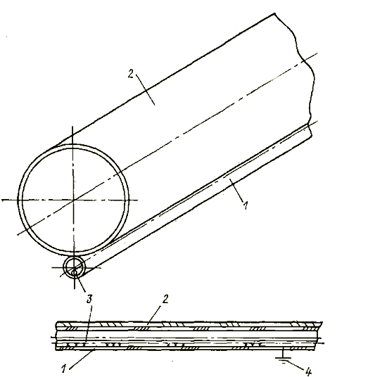
Figure 3.1 - diagram of a heating pipeline on the basis of surface effect:
1 – auxiliary (heating) pipe; 2 – heating pipeline; 3 – conductor (heat resistant) cable; 4 – grounding
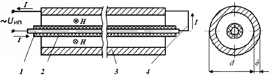
Figure 3.2 – Principle of induction-resistance heating system:
1 – wire conductor-inductor; 2 – electric insulation of wire; 3 – steel tube; 4 – connection of conductor tube and the end of the line
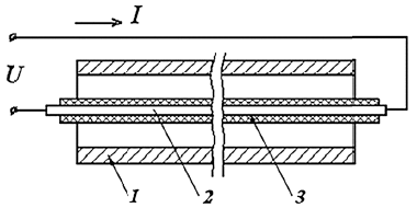
Figure 3.3 – the Principle of induction heating systems:
1 – ferromagnetic tube; 2 – wire conductor-inductor; 3 – electrical insulation of the conductor
3.2 Heating systems with heating cables
Today, the following technologies are used electrical heat tracing using heating cables:
- Systems with constant power:
- cables mineral insulated (MI);
- polymer cables with a constant output;
- cables parallel type;
- heating tape pre-calculated length.
- Self-regulating system.
- Power limiting system.
Principle of operation of systems with constant power based on the allocation of core heat through the resistance. Depending on the required resistance of the cable cores are made of various materials. Disadvantages of systems with constant power: the overlap of the cables is not allowed; a fault in one place, de-energizes the entire circuit.
Main element self-regulating heating cables – heating element is made of polymers mixed with conductive carbon.
This compound is located between the conductive cores and the conductive occur in it track
. Their number varies depending on the temperature change.
Principle of operation is based on the fact that with decreasing ambient temperature, the heating element is compressed at a microscopic level, which leads to
reduction of resistance (number of tracks
is increased). On the contrary, with increasing temperature, the heating element expands, which reduces conductive tracks
. The result of the heating cable allows multiple cresting (at the point of intersection of the impedance increases).
Disadvantages of self-regulating cables is their starting current (~2,5-4Ін) and the maximum maintain temperatures to 150 °C.
Self-limiting heating cables consist of heating element alloy with a high specific resistance, helically wound around the two parallel cores. Insulation removed from a fixed step variable on each of the cores. The distance between the points of contact of current-carrying lived with the heating element determines the length of the heating zones.
A positive temperature coefficient heating element allows it to adjust the heating capacity depending on the temperature of the system, which is mounted on the heating cable. At lower ambient temperature, the resistance of the heating element decreases, which leads to the growth of heat output. With increasing temperature the resistance rises, limiting the heating capacity. This effect allows you to mount the self-limiting heating cables with only a single overlap, since the temperature of the heating element at the intersection will be reduced. For example, this factor affects the binding of gate valves of pipelines.
Conclusion
In this work, the collection and evaluation of information on industrial electric heating will be performed, the design of electrical heating, the selection of electrical equipment for connection will be considered. When writing this essay, the master's work is still under development. Final completion: June 2018. Full text of the work and materials on the topic can be obtained from the author or his supervisor after the given date.
References
- Лазаревич Д.Э., Якимишина В.В.:
Использование электрообогрева на промышленных предприятиях
.Инновационные перспективы Донбасса/III Международной научно-практической конференции – Донецк, ДонНТУ – 2017, Секция 2, с. 153 – 160. - Струпинский М.Л. С87 Проектирование и эксплуатация систем электрического обогрева в нефтегазовой отрасли: справочная книга / М.Л. Струпинский, Н.Н. Хренков, А.Б. Кувалдин. – М.: Инфра-Инженерия, 2015. – 272 с.
- Yurkanin R. М. Safety aspects of electrical systems. — Chemical Engineering, 1970, v. 77, N 27, p. 164, 166.
- Фонарев 3. И. Электроподогрев трубопроводов, резервуаров и технологического оборудования в нефтяной промышленности. — Л.: Недра, 1984. — 148 с.