
Contents
- 1. Description of the Manus robot manipulator.
- 2. The purpose and tasks of work, the required results.
- 3. Development of the hardware.
- List of sources
1. Description of the Manus robot manipulator.
In this project are taken as a basis mechanics and the drive from the Manus robot manipulator. This manipulator is developed and manufactured by the Dutch company and intended for installation on wheelchairs.
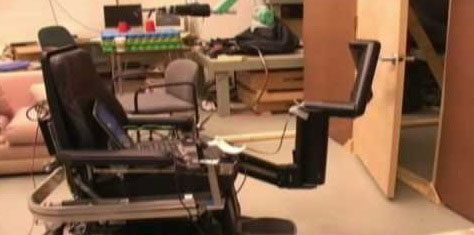
Figure 2.3 – The Manus Manipulator installed on the wheelchair.
Manus can have own operating computer and the panel joystick for manual control that allows to carry out the actions not available to persons with limited opportunities owing to their physical features. For example, this manipulator can give various objects remote from a chair, within a zone of reach of the manipulator. Except manual control from the joystick, the computer (controller) serving this manipulator allows to connect cameras and can process the received image by means of algorithms of machine sight. This feature allows the manipulator to perform not only the operations set by the operating person, but also to automate some tasks. Also operating computer allows to combine the above described types of management (in original documentation on Manus this type of management is called Collaborative Control). Joint management allows to achieve the best indicators in the accuracy of positioning of capture of the manipulator because the task arriving from the joystick from the operating person is corrected on certain algorithms proceeding their surrounding situation. The analysis of a surrounding situation is made by means of algorithms of machine sight on the basis of the data arriving from cameras. Such corrections of a task allow to choose the most optimum trajectory and also allow to bypass obstacles automatically.
On the figure 2.4 and 2.5 photos of our copy of the Manus manipulator are submitted.
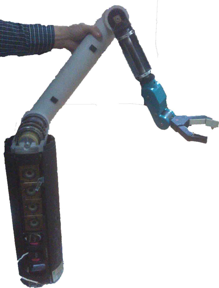
Figure 2.5 – Photo of the Manus manipulator.
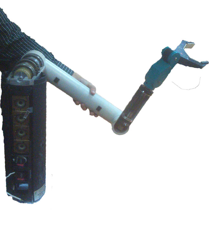
Figure 2.5 – Photo of the Manus manipulator.
This manipulator consists of four mobile links, each of which has the axis of rotation and also the gripping device (skhvat) fixed on the end of the last of links. Skhvat of the manipulator also has a rotation axis. Such configuration of the manipulator provides 6 degrees of freedom. The size of this manipulator can be estimated approximately according to the photo, and its weight – about 15 kg.
Usually, in similar robots 2 types of drives can be applied: on the basis of SDPM – synchronous motors with permanent magnets, or on the basis of DPT – direct current motors [5].
In the manipulator considered in this project are applied the drive of the second type – on the basis of direct current motors with excitement from permanent magnets. Such decision has a number of advantages: rather simple SUEP in comparison with drives on the basis of SDPM and also much lower cost of both engines, and power converters to them. Except advantages this system has a shortcoming – lower dynamics (relatively SDPM). However, in a case with the Manus manipulator this shortcoming has no value as the robot was designed for installation on wheelchairs for the purpose of the help to the people limited in the movements, and in such application high dynamics of system and is not required.
The engines of all joints used in the Manus manipulator – identical, Maxon of the maxon DC motor series. The appearance of this engine is presented in the figure 2.5.
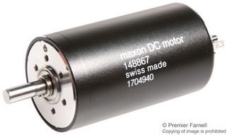
Figure 2.5 – Appearance of the engines installed in the manipulator.
Key parameters of this engine are specified in table 2.1.
| Rated voltage | 24 V |
| Rated current | 0.7 And |
| Rated speed | 8670 rpm |
| Idling current | 0.05 And |
| Maximum admissible current | 2 And |
Table 2.1 – Parameters of the maxon DC motor engine.
From motors to links of the manipulator are applied a reducer with planetary transfer to transfer of rotation. This type of reducers has many advantages over others, such as compactness and reliability. Reducers identical established on all engines also have transfer number 1:800.
Except engines and reducers the sensors of speed of rotation of engines installed directly on shaft of engines enter the initial system of the electric drive. Type of the used sensors – an incremental enkoder with optical switching. Resolution of the used sensors 100 imp / about that in general is rather small value for creation of qualitative position system. But considering the fact that the sensor is installed to the reducer having transfer number 1:800 – such permission will be more than enough.
All above-mentioned elements were taken as a basis for the thesis (the case, motors, reducers, speed sensors) and on the basis of the available element base the system considered in this work will be constructed.
2. The purpose and tasks of work, the required results.
Taking into account all above in the degree project it is planned to develop a control system of the robot manipulator described in point 2.3.
Tasks of the master project:
- To execute modeling of electric drives of the robot manipulator.
- To execute modeling of mechanics of the robot manipulator.
- To develop the hardware decision (a power part) for control of robot manipulator drives.
- To develop the operating program allowing to operate robot manipulator drives with ensuring maintenance of a standard position for each of drives.
3. Development of the hardware.
The basic of elements of the hardware is the power converter – the engine driver. Several schemes, the most functional of which the N-bridge, are applied to control of direct current motors. The generalized scheme is submitted in fig. 4.1.
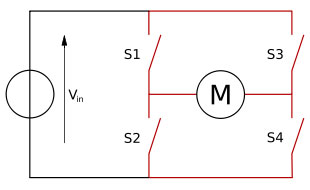
The figure 4.1 – the generalized scheme of the N-bridge.
This scheme consists of four keys included in pairs consistently, between couples the engine (an anchor chain) turns on. Two top keys are connected to the positive tire of the power supply, two lower keys – to the negative tire of the power supply. It is necessary for operation of the engine that two keys, for example S1 and S4 were included, in that case current will proceed from the power supply through S1 key, further through an anchor of the engine and through S4 key. At the same time, two others a key have to be closed. For change of the direction of current in an engine anchor (and, respectively, and the directions of rotation of the engine) it is necessary to close open keys of S1 and S4, and to open keys of S2 and S3.
Depending on the required switching speed as keys either the relay, or transistors can be used. In the developed project the high speed of switching (since engine management will be exercised by means of PWM) is required, and, therefore, as keys transistors have to be used.
The necessary scheme can be collected from separate transistors. But it – is inexpedient. Because today chips – drivers of engines which include the necessary scheme of the N-bridge and also a binding for power keys were widely adopted. Such decision simplifies and reduces the price of process of development of SUEP.
For the developed project from available in the market the L298 engine driver chip is chosen. The block diagram of the l298 driver is shown in fig. 4.2.
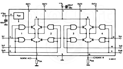
Figure 4.2 – Block diagram of the l298 driver.
Proceeding from the block diagram of the driver it is visible that the chosen chip comprises two full-bridge drivers that allows to connect two engines to one driver that in turn will allow to save the place on the printed circuit board of the driver since in the developed project 7 engines are used, but chips of drivers will be four enough. Besides, this chip has a conclusion for connection of the sensor of current of shuntovy type that is necessary in certain cases.
In documentation it is specified that for work this chip needs only several external elements, such as: the additional power supply 5B (it is necessary for food of logical chains in a chip) and also 8 external diodes which will perform function of protection of the driver and will assume the return EMF of the engine. Parameters of a chip L298 are specified in table 4.1.
| Supply voltage | 5 – 46 V |
| Logic supply voltage | 5 B |
| Collector current long | 2 And |
| Collector current pulse | 3 And |
| Working frequency | 25 – 40 kHz |
| Entrance tension of logic | 3 – 5 B |
Table 4.1 – parameters of the maxon DC motor engine.
As criteria of the choice of this chip served the electric parameters of the engine specified in the previous section and also that fact that this chip is most widespread in the market and, as a result, has low cost concerning competitors.
The control of this driver requires 3 entrance signals which will be given from the microcontroller: 1 – permission of work, 2 and 3 directions of rotation of the engine.
Except a power chip also use of the sensor of current, for measurement of current of an anchor is required. Use of the shuntovy sensor of current of L298 connected to a special conclusion in this case does not approach as there are two essential shortcomings – lack of an outcome on food and impossibility of measurement of the direction of current but only its sizes.
For the listed above reasons it is decided to use the current sensor on Hall's effect. These sensors provide a galvanic outcome of a power part and the measured exit, and it means that the measured exit can be connected to microcontroller ATsP without risk of breakdown in case of refusal of any component.
From available on sale at the time of the choice of sensors of current on Hall's effect, only the ACS758 model of Allegro Microsystem approaches. Only this sensor has a bipolar entrance that in turn will allow to measure not only the size of current, but also its sign. In the figure 4.3 the scheme of connection of the sensor from documentation on it is submitted.
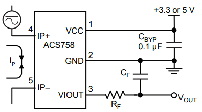
Figure 4.3 – Scheme of connection of the ACS758 sensor.
This sensor works as follows: conclusions 4 and 5 join in the measured chain, on a conclusion 1 and 2 food moves, and from a conclusion 3 stress which level is proportional to the measured current is removed. And, the output signal not from 0 V to supply voltage, and under the special law changes: to the zero measured current, there will correspond output tension equal to a half of supply voltage. And at course of current in a measuring chain amplitude of an output signal will increase (or to decrease, depending on the direction of course of current) by the value of 40 mV increased on 1 A measured current. For example: power supply of the sensor of 5 V, at the zero measured current at the exit of the sensor will be a signal 2,5 B, and at course of current 10 A in the measured chain, the output signal of the sensor will be 2,5 B + 40 mV? 10 A.
One more advantage of this sensor is that it can be powered, both from 3.3 B, and from 5 V that will allow to use microcontrollers of different architecture. Key parameters of the sensor of current are specified in table 4.2.
| The maximum measured current | +– 50 A |
| Sensitivity | 40 mV / And |
| Supply voltage | 3.3 – 5 B |
Table 4.2 – Key parameters of the sensor of current
As the maximum current of the engine used in the project does not exceed 2 A, it is possible to consider that the maximum range of output tension from the sensor of current will be 1.55 – 1.75 In at food from a source of 3.3 Century. This range will be expedient to be expanded since ATsP measures in microcontrollers from zero to supply voltage with the final permission (for example 10 bits), so at such range the accuracy of measurement will be low, and respectively and the accuracy of regulation of current will also be low.
For expansion of range of output tension the operational amplifier is applicable and we will connect it according to the scheme of strengthening with signal shift. The scheme is submitted in the figure 4.4
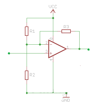
Figure 4.4 – Scheme of turning on of the operational amplifier.
This scheme allows to scale a signal from the sensor so that at an exit from the sensor of a signal 1.55 In at the exit of the operational amplifier will be a signal close to zero, and at an exit from the sensor 1.75 B signal level from an exit of the operational amplifier will be close to tension of its food that will allow to connect it to ATsP of the microcontroller and to receive more exact measurements. Calculation of face values of resistors will not be given in the paper. On the basis of the conclusions given above and the choice of components the general scheme of the driver of the engine submitted in fig. 4.5 is developed.
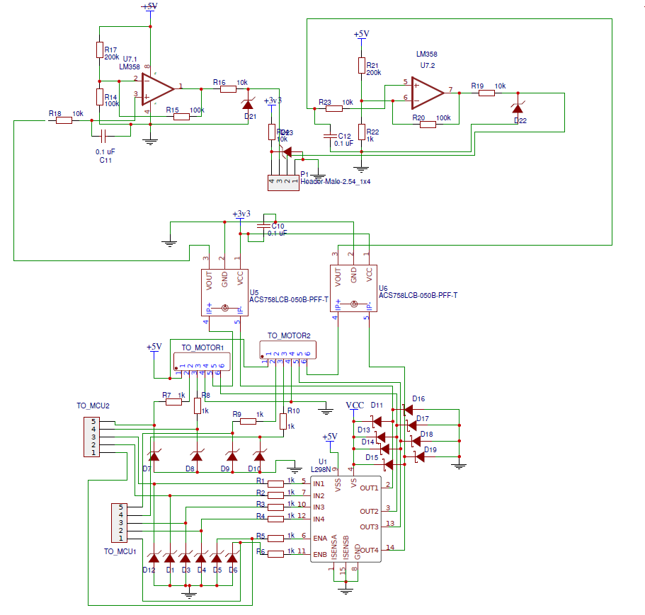
Figure 4.4 – Scheme of the driver of the engine.
This scheme turns on the driver for two engines, two sensors of current and two operational amplifiers. The connectors TO_MOTOR – sockets of connection of engines and enkoder, the connectors TO_MCU – the sockets for connection to the microcontroller including three lines of control of the driver (described in the previous section) and two lines for signals from an enkoder. Diodes in a driver binding – any high-speed diodes on tension and current exceeding tension and current of the engine, stabilitrons on pilot lines – protective stabilitrons with the stabilization tension equal to working tension of the operating microcontroller, necessary for protection of the microcontroller in case of breakdown of the power driver.
List of sources
- Lectures. Classifications of systems of coordinates [An electronic resource]. – Access mode: http://baumanki.net/lectures/.
- Industrial robot [Electronic resource]. – Access mode: https://ru.wikipedia.org/wiki.
- The analysis of the current state of use of robots in the industry [An electronic resource]. – Access mode: https://ru.wikipedia.org/wiki
- Classification and structure of industrial robots [Electronic resource]. – Access mode: http://www.metal-working.ru/.
- Collaborative Control of the Manus Manipulator [Electronic resource]. – Access mode: https://link.springer.com/.
- Enhancing the usability of the MANUS manipulator by using visual servoing [Electronic resource]. – Access mode: http://citeseerx.ist.psu.edu/.
- Assistive Robotics [Electronic resource]. – Access mode: http://eecs.ucf.edu/.
- Anuchin A. S. Control systems Electric drives / Anuchin A. S.: MEI publishing house, 2015. – 43 pages.
- Manipulator (mechanism) [Electronic resource]. – Access mode: https://ru.wikipedia.org/wiki/.
- Fundamentals of robotics/S. Schilling: Prentice hall publishing house, 2005. – 90 pages.