
Abstract
Introduction
- 1. Analysis of prototypes
- 2. Description USAPR ("CAD_Electric_Education")
- 3. Own needs of power plants;
- 3.1. Features of own needs of thermal power plants
- 3.2. Features of own needs of nuclear power plants
- 3.3. Features of their own needs hydraulic power plants
- 4. The technique and algorithm of calculation of currents of KZ
- 5. Conclusion
- List of sources
Introduction
Short circuit is the emergency mode of operation of the electrical installation arising from the violation of insulation of live parts. Short–circuit current is usually many times more operating current and may result in live parts inadmissible dynamic stress and overheating. In addition, if a short circuit may lead to the termination of supply of consumers, which is unacceptable in networks of own needs of power plants.
1. Analysis of prototypes
The main advantages of CAD in any industry are the reduction of the complexity of the design, reduction of errors in projects and reduced investment in project developments. Today there are many domestic and foreign counterparts, allowing to automate the design in different industries. During the Soviet years, widespread CAD received in architecture and construction, and mechanical systems in mechanical engineering, shipbuilding and the aerospace industry. In the electric power industry development of CAD systems has focused on relatively simple objects (a small step–down substations) and in relation to simple design procedures. Table 1 shows the analysis of the most used CAD system in the power industry. N it shows a price evaluation of several CAD programs for 2013 Prices are impressive even for big corporations, not to mention the local design institutes and Universities. In addition, none of the programs has a complete set of design procedures required to complete the entire project scope.[1]
2. Description USAPR (CAD_Electric_Education
)
As a platform for creating educational CAD software used is one of the best graphic editors AutoCAD, among whom created a graphical database of images of basic elements of electrical circuits with voltage above 1 kV. Software USAPR built on the AutoCAD object model and the use of internal algorithmic programming languages AutoLisp, VisualLisp, and language create dialog boxes DСL.[2]
| CAD name | Developer | Base Platform | CAD Cost | Cost of the base platform | Total cost per 1 working place |
|---|---|---|---|---|---|
| Project Studio CS Электрика v.5 | CSoft | AutoCAD | One workplace – 70 000 rubles; Hardware protection key – 1 500 rubles | One workplace – 81 500 руб.; Annual update– 14 000 rubles | 153 000 rubles + annually 14 000 rubles |
| WinELSO | Russian industrial | One workplace – 62 500 rubles | 144 000 rubles + annually 14 000 rubles | ||
| MagiCAD Power supply | MagiCAD | One workplace – 190 000 rubles | 217 500 rubles + annually 14 000 rubles | ||
| ELF | Lira service | One workplace – 24 200 rubles | 105 700 rubles + annually 14 000 rubles | ||
| HTE | Company POINT | One workplace – 110 000 rubles; Annual update – 24 000 rubles. | 191 500 rubles + annually 38 000 rubles | ||
| nanoCAD Electro | Nanosoft | Custom graphics core | One workplace – 15 000 rubles. | 15 000 rublesежегодно | |
| CADprofi | CADprofi Germany GmbH | Bricscad | One workplace – 11 100 rubles. | One workplace – 13 300 rubles | 24 4000 rubles. |
Table 1 – financial assessment of CAD programs
Information support of USAPR based on the use of spreadsheets, MC Exel. It includes background information on the basic electrical elements: generators, power transformers and autotransformers, circuit breakers and disconnectors, current transformers, and cable products and busbars. Information sources were the latest designs of educational–methodical literature of the CIS countries, as well as data of the official websites of the leading hardware manufacturers (ABB, Simens, Shneider electric, General Electric, Alstom Grid, etc.).
Special attention is paid to equipment of the wind farms because of the great importance of the question of alternative energy. A character database of wind turbines and transformers of wind turbines (wind turbines), power cables, recommended for use in systems and networks with unconventional energy sources. Mode edit the information (in electrical engineering this is particularly relevant in view of the fact that constantly produced new equipment with the production symetra old, moderniziriruyutsya some models).[3]
Software, USAPR includes methods for solving systems of linear and nonlinear algebraic equations by the method of square roots, using the property of symmetry of the matrices of coefficients. Applied a variant of the method for working with sparse matrices, which leads to high performance design features. In tracing cables are used Dijkstra an efficient algorithm for determining minimum distances between nodes in directed graph.
Scientific novelty of the different created design procedures for the study of transient modes of operation of mechanisms of own needs of power plants, the method of synthesis of a mathematical model glubokovodnykh HELL in his single–loop equivalent circuit. The method is based on minimization of variance of initial and calculated values of the stator currents and torques at set points slip by means of the solution of systems of nonlinear algebraic equations.[4]
Under the pilot project CAD_Electric_Education has 4 design procedures:
- calculate short circuit currents in electrical installations with voltage above 1 kV and selection of basic power equipment;
- study of the modes of start–up and self–starting motor system of own needs of thermal power plants;
- trace the cables to the outdoor switchgears high–voltage substations;
- power distribution in a ring schemes output a powerful modern wind power plants.
The advantages of USAPR include the use as the output source of design diagrams generated by the students on the screen. These output and input data tables and results of the design procedures used today correspond to GOST CIS countries.[5]
3. Own needs of power plants
Installation own needs is an important element in power plants and substations. Corruption in system of own needs repeatedly led to the initiation of operation of power plants and to the emergency condition of power systems.
The composition of elektroprijenos own needs depend on the type of plant (substation), from fuel, power units and other. Table 1.1 shows the indicative values of the maximum load their own needs , related to the installed power plant capacity and energy costs for own needs , and related energy produced by the power plant for the year , %.The choice of electrical circuits for their own needs is carried out taking into account the composition and characteristics of elektroprijenos, power drive mechanisms, requirements to reliability of power supply to individual consumer groups, and other. Cost allocation of electricity for certain groups of consumers, CHP and CES are given in table 1.2.[6]
Elektrodinamiki their own needs for their effect on the technological mode of the installation are conventionally divided into responsible and irresponsible. Responsible include elektrodinamiki, the output of the procedure which may lead to the initiation of normal operation or accidents at the power plant or substation. Stacieinatlanta need especially reliable nutrition.
The main reason of mechanisms of own needs there are asynchronous squirrel cage motors with different run direct on line starting. For slow–moving mechanisms (formation of the mill), and also very powerful mechanisms find application for synchronous motors. For mechanisms that require the regulation of the frequency within wide limits, used DC motors, and induction motors with thyristor control.
Power plants usually take two degrees of tension of own needs: high (3.6 or 10 kV) – to supply powerful elektroprijenos and lower (380/220 V with grounded neutral) is to supply small elektroprijenos. The adoption of one or another system of stresses depends on the technical and economic characteristics of electric motors. At one and the same power asynchronous motors, lower voltage is cheaper than motors of a higher voltage. However, the design and operating (level of short–circuit currents., the conditions of self–starting) consideration of increasing the power of engines leads to the need of increasing their nominal voltage.
НNow the industry produces motors 380 V with power up to 400 kW and motors 3 – 6 kV, starting with capacity 160 – 200 kW. Motors 10 kV can have a composite technical and economic indicators, starting with the power of 630 kW.At the CES, CHP, and nuclear power plants high voltage system to their own needs, usually taken equal to 6 kV. At the CES units with a capacity of 800 – 1200 MW, respectively, with the major mechanisms for their own needs appropriate application of voltage of 10 kV. Hydro electric engine the basic mechanisms powered from the mains 380/220 V, large motors and mechanisms from a network of 6(10) kV. At the substations in the system's own needs is taken a voltage of 380/220 V. Extreme power transformers 3 – 10/0,4 kV 1000 kVA is taken when the short–circuit voltage of 8 %. Maximum power is mostly limited by the switching capacity of the machines 0,4 kV.
| Electrical installation type |  |
 |
|---|---|---|
| TES: | ||
| dust–coal | 8–14 | 8–10 |
| gas oil | 5–7 | 4–6 |
| КЕS: | ||
| dust–coal | 6–8 | 5–7 |
| gas oil | 3–5 | 3–4 |
| АЕS: | ||
| with gas coolant | 5–14 | 3–12 |
| with water coolant | 5–8 | 4–6 |
| GES: | ||
| low and medium power | 3–2 | 2–1,5 |
| high power | 1–0,5 | 0,5–0,2 |
| SUBSTATION: | ||
| district | 50 – 200 kW | – |
| nodal | 200 – 500 kW | – |
Table 2.1 – energy Costs for own needs
3.1 Features of own needs of thermal power plants
Composition of own needs of thermal power plants depends on the cycle (vocational schools, GTU, CCGT), the type of fuel burned and the availability of district heating. Roughly the power of the motor SN in relation to the capacity of the generator is 8–14 % for coal–fired CHP; 5–7% for oil–gas CHP; 6–8 % for the coal–fired KES; 3–5 % for gas–oil condensing power plant. The vast majority of cases, the actuator mechanisms of SN are asynchronous motors with squirrel cage rotor, operating at a voltage of 6.3 kV (power more than 200 kW) and 0.4 kV (power less than 200 kW). Rarely, the actuator is a synchronous AC motor, DC motor, a separate steam turbine of small capacity. Synchronous motors are used on coal–fired thermal power plant to drive the mills. Such engines are requirements for successful self–in the case of short power interruptions as de. This is due to the intermediate hopper of coal dust, which by its design resembles a narrowing funnel. During shutdown of the mill, the coal dust is gradually settling in the bunker, it will continue to do in the furnace of the boiler. The DC motors are applied in the case that the Executive mechanism is responsible, subject to regulation in a wide range, relatively low power. It is mechanisms such as pumps shaft seals of a generator, pumps bearing lubrication of turbine and generator, the PSM mechanisms of a nuclear reactor. The turbine is used to rotate the nutrients and booster pumps powerful units. Feed pumps have the greatest specific power consumption among the other mechanisms of SN. For example, on the TES unit 200 MW total power mechanisms of SN is equal to 27 MW, including the capacity of the two nutrient pumps 2 ∙ 4 = 8 MW, which is about 30 % of the load of SN unit. A turbo can significantly reduce the electric load of their own needs, to create high–speed rotation, to adjust the performance of the mechanism. It should be emphasized a specific cycle gas turbines where there is no majority of such mechanisms in the cycle of vocational schools. Recall that in the cycle GTU the only mechanism (compressor), has a counterpart in the cycle of the vocational school (the blower fan) rotates not at the expense of the actuator, and due to the gas turbine. Therefore, the electrical power of the mechanisms of SN in the cycle of the gas turbine is much less than in the cycle of vocational schools in a specific ratio to the power unit.[7]
3.2 Features of own needs of nuclear power plants
Own needs NPP are different from the SN KES the presence of additional mechanisms of the reactor, the most important of which is the main circulation pump (MCP), feed the coolant in a nuclear reactor. Units with bn reactors have the additional load of the electric heating of the sodium circuits. Roughly the power of the motor SN in relation to the capacity of the generator is 5–8 %. From the point of view of security of supply to their own needs NPP are subject to more stringent requirements than in the case of other power plants. In accordance with [11] consumers of SN NPP are divided into 3 groups. The first group – consumers of direct and alternating current, does not allow for safety or the safety of the main equipment of the power supply failure of more than a fraction of a second in all modes including complete disappearance of the alternating voltage from the working and standby transformers SN, and requires the availability of power supply after actuation of emergency protection (AZ) of the reactor. Consumers of the first group are powered by emergency power systems. In normal and emergency mode, these consumers receive power from the uninterrupted power supply units. The first group includes the instrumentation and automation of the reactor protection, emergency pumps lubricate bearings and turbine shaft seal generator, reactor coolant pump with a small inertial mass, the CPS drives, etc. the Second group of consumers of the AC, allowing the interruption of power on time, defined by the terms of the security or safety of the underlying hardware and requires the availability of power supply after tripping AZ reactor. Consumers of the second group are connected to the system of reliable power supply. In normal operation these consumers get power supply from working and reserve transformers of own needs in an emergency – from stand–alone diesel generators (or, less frequently, from hydropower, gas turbine). The second group includes mechanisms of cooling of the reactor and the fault localization a variety of modes including the maximum design accident, the emergency feed pumps, fire pumps, sodium reactor coolant circuits of the reactor. The third group – consumers AC, non–break power on time, automatic, and does not require the obligatory presence of power supply after tripping AZ reactor. Consumers of the third group connected to the system for normal operation. In normal operation these consumers receive power from the working and backup auxiliary transformers, emergency operation occurs the breakdown data of consumers. The third group includes MCP with a large inertial mass, as well as most of the mechanisms of the cycle of vocational schools. Own needs of thermal power plants correspond to the reliability of own needs of the third group of nuclear power plants. If for thermal power plants power supply of own needs are TSN, RDSN and battery, then NPP is TSN, RDSN, diesel generators and uninterruptible power supply units. From reliability considerations, the number and capacity of workers and backup TSN is higher than for TPP. Diesel generators are run for a relatively long time – at least 10–15 seconds, but after that long to produce the necessary power. Uninterruptible power supply units with the disappearance of the voltage from the grid switch power to a backup source – the battery. Moreover, this occurs instantly, without breaking sine wave DC. The battery capacity is limited to several tens of minutes.
3.3 Features of their own needs hydraulic power plants
Due to the simplicity of the technological process of electricity production at hydroelectric power plants, consumption for own needs much less than for fossil and nuclear power plants, and is 0.5–3% of installed capacity. Smaller values relate to more power units of the HPP. For HPP, typical of a large proportion of plant load compared to the aggregate. The latter is no more than 30% of total consumption for own needs. Consumers aggregation of SN are located in the immediate vicinity of the unit and are fed into voltage 0.4 kV and 6.3 kV and less. Consumers aggregation of SN are: pumps process water units – water lubricated turbine bearings, oil coolers, and bearings of the thrust bearing of hydro–generator, hydro generator coolers; pumps and compressors oil charge installation (MNU) and a regulating system hydraulic turbine; pumps pumping water from the cover of the turbine due to leaks in the flow path of hydraulic unit; the fans and pumps of the cooling system transformer; auxiliary devices of the excitation system. Consumers plant SN apply to all of the entire plant and feed on the voltage of 0.4 kV.
4. The technique and algorithm of calculation of currents of KZ
In the first stage, the graphic image of the design scheme created by the user on the screen of the monitor (see for example Fig. 4.1),
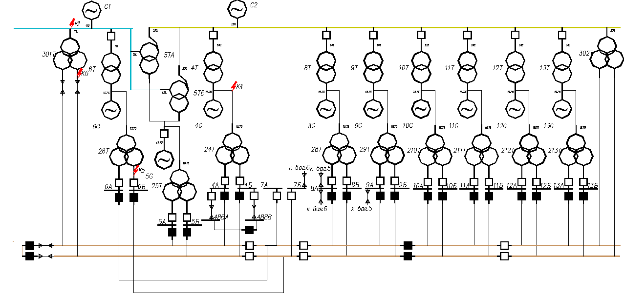
Figure 4.1 Diagram of thermal power plant
transformed into a mathematical model in the form of a directed graph. Last identificireba the list of branches of the circuit spe. Then, from the list spe are formed right triangular matrix of nodal conductances and the vector specifying the node currents from EMF. The algorithms of these procedures are described in the previous section up.For the calculation of symmetrical three–phase short–circuit faults in matrix Ybu establishes a shunt circuit (Ykz) with a large conductivity (0.0 –100000.0). The shunt is switched on in parallel to other branches associated with a node in KZ. Programmatically it is implemented in the assignment operator setq figure 4.2

Figure 4.2 – Fragment of the shunt short–circuit
After that are the voltage at nodes of the calculated scheme by solving the basic vector–matrix equations the method of nodal voltages (see formula 4.1). According to the known voltages determined by the currents of short circuit in the active branches and the total short–circuit current in the shunt circuit.
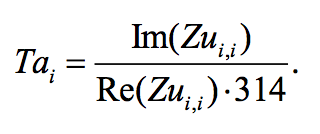
The special features of the algorithm include finding values of time constants and attenuation of the aperiodic components of The fault current used to calculate the impact of fault current, its aperiodic component and a heat pulse of short–circuit current. To determine That all calculations are performed with complex impedances. The latter required the development of missing AutoLisp functions work with complex numbers.
Time constant of damping of the aperiodic component of the short circuit current is determined by active and reactive components of the complex values of the short circuit current.
Формула 4.1
According to the known dependences [3] determined all the other components of the fault current, and its thermal pulse. Aperiodic component of the fault current by the time the switch is :
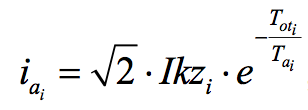
Формула 4.2
The instantaneous shock of the short circuit current:
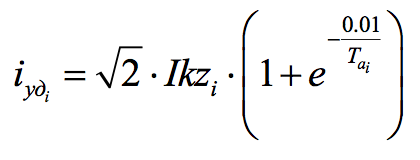
Формула 4.3
And thermal pulse short–circuit current:
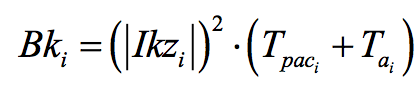
Формула 4.4
where: Tpac=Tpz+Tnv– estimated time of short–circuit,Тpz – time major neustrategy protection; Tnv – a full time mute switch.
5. Conclusion
When writing this essay, the master's work is not yet complete. Final completion: March 2018. The full text of the work and materials on the topic can be obtained from the author or his supervisor after the specified date.
List of sources
- Учебная САПР электрической части станций и подстанций. [учебное пособие] / Павлюков В.А., Ткаченко С.Н., Коваленко А.В. – Харьков: ФЛП Панов А.Н., 2016. – 124с.
- Официальный сайт АББ в России[Электронный ресурс].
- Миллер Р. Теория переключательных схем / Р. Миллер. – М.: Наука, 1971. – Том 2: Последовательностные схемы и машины. – 304 с.
- Зуев, С. А. САПР на базе AutoCAD – как это делается / С. А.Зуев, Н. Н. Полещук – СПб.: БХВ–Петербург, 2004. – 1168 с.
- Полещук, Н. Н. AutoCAD разработка приложений, настройка и адаптация / Н. Н. Полещук. – СПб.: БХВ–Петербург, 2006. – 992 с.
- Короткие замыкания и выбор оборудования : учеб. пособие для вузов / И. П. Крючков, В. А. Старшинов, Ю. П. Гусев [и др.] ; под ред. И. П. Крючкова, В. А. Старщинова – М.: Изд. дом МЭИ, 2012. – 568 с.
- Баков, Ю. В. Проектирование электрической части электростанций с применением ЭВМ: учеб. пособие для вузов / Ю.В. Баков. – М.: Энергоатомиздат, 1991. – 272 с.