
Abstract
Содержание
- Introduction
- 1. Theme urgency
- 2. Scientists involved in solving this problem
- 3. Modern problems of using protective residual current devices (RCDs) in networks up to 1000 V.
- References
Introduction
The increasing use of electric power in all areas of human activity, the steady increase in the power-to-weight ratio of labor, and the sharp increase in the number of electrical appliances in everyday life and in industry naturally led to an increase in the risk of electric shock to a person.
One of the most important problems of modern electric power industry is the creation of safe electrical installations. Since, despite the tremendous efforts of electric power engineers, tens of thousands of people die every year from electric shock, without having a direct relationship to the profession of electric power. Such statistics of accidents exist for people of other professions who had direct or indirect contact with devices in which the insulation of current-carrying parts is broken or connected to a faulty power supply network.[1]
1. Theme urgency
Protecting the life and health of people, as well as their property from electric shock, is a task of paramount importance throughout the world. In all countries where the power supply is highly developed and the most ordinary consumers have access to the power grid, the highest requirements for electrical safety are applied to the degree of protection of consumers from electric shock.
Electric current does not have any physical signs or properties on which a person could feel it with sense organs, which aggravates its danger to man. From the very beginning of industrial application of electricity, scientists from all over the world were engaged in studying the effect of electric current on a person and the consequences of this impact.
Electro-trauma is a significant proportion of the total number of accidents. Electricians and ordinary users are aware of a large number of deaths or severe injury to people from electric shock or fires and fires caused by electrical and wiring faults.
2. Scientists involved in solving this problem
A great contribution to the study of this problem was made by well-known scientists: HHEgyptien, LPFerris, DGKing, HBWilliams, WBKouwenhoven, CFDalziel, S.Koeppen, G.Irresberger, H.Hofherr, JTHarley, G.Biegelmeier, E.Reindl , F.Smola, BJSimpson, J.Jacobsen, M.Ohasi, T.Kawase, A.P. Kiselev, V.E. Manoilov, AI Sidorov, Yu.V.Sitchikhin, B.A. Knyazevsky, V.I. Shchutskiy and many others.
3. An approach to the unification of synthesis of Moore FSM on FPGA
In the 1950s scientists unambiguously established that when an electric current is applied to a person, the heart is the most vulnerable organ.
Fibrillation (erratic contractions of the muscles) of the heart can occur even at low current values. The versions of asphyxiation, paralysis of muscles, brain damage as primary causes of death in case of electric shock were dropped.
It was also found that the result of the action of an electric current on the human body depends not only on the current value, but also on the duration of its course, the current path through the human body, and also, to a lesser extent, on the individual qualities of man, the frequency of the current, coefficient of ripple and other factors.
The electrical resistance of the human body depends on the skin's moisture content, the size of the contact surface, the way the current flows through the body, the physiological characteristics of the body, and a number of other factors.
It is known that the resistance of the internal organs of man does not exceed 500-600 Ohm. [1]
The skin resistance in the wet state is extremely low 10-20 ohms. When determining the electrical safety conditions in the electrical installation, the resistance of the human body is taken as 1000 Ohm.
The current values that should identify such a device are shown in Table 1. [5]
Table 1 - The values of the currents flowing through the person and their action.
Current value, mA |
Nature of impact |
|
AC 50 Hz |
DC/p> |
|
| 0,6—1,6 | The beginning of sensation - a weak itch, a tingle of the skin under the electrodes | Is not felt |
| 2—4 | The sensation of the current also extends to the wrist of the hand, slightly reduces the hand. | Is not felt |
| 5—7 | Painful sensations are amplified in the entire hand, accompanied by cramps; weak pains are felt in the entire arm, up to the forearm. Hands, as a rule, can be torn off from electrodes | Start feeling. The impression of heating the skin under the electrode |
| 8—10 | Severe pain and cramps in the entire arm, including the forearm. Hands are hard, but in most cases still can be torn from the electrodes | Increased sensation of heating |
| 10—15 | Hardly bearable pains in the entire arm. In many cases, hands can not be torn from the electrodes. With increasing duration of the course of the current, the pain intensifies | A further increase in the sensation of heating both under the electrodes and in the adjacent regions of the skin |
| 20—25 | he hands are paralyzed instantly, it is impossible to break away from the electrodes. Severe pain, breathing is difficult | An even greater increase in the sensation of heating the skin, the appearance of a feeling of internal heating. Minor contractions of the arm muscles |
| 25—50 | Very severe pain in the arms and chest. Breathing is difficult. With long-term current, paralysis of breathing or loss of heart activity with loss of consciousness | Feeling of intense heat, pain and cramps in the hands. With the separation of the hands from the electrodes, barely tolerable pain occurs as a result of convulsive muscle contraction |
| 50—80 | Breathing is paralyzed after a few seconds, the heart is broken. With prolonged flow of current, cardiac fibrillation may occur | Feeling of very strong surface and internal heating, severe pain in the entire arm and in the chest area. Difficulty breathing. Hands can not be torn from the electrodes due to severe pain in case of contact failure |
| 100 | Fibrillation of the heart after 2-3 seconds; a few seconds later - paralysis of the heart | Respiratory paralysis with prolonged current flow |
| 300 | ТSame action in less time | Fibrillation of the heart after 2-3 seconds; a few seconds later - respiratory paralysis |
| более 5000 | Breath is paralyzed immediately - in fractions of a second. Fibrillation of the heart, as a rule, does not occur; it is possible to temporarily stop the heart during the current flow. With prolonged current flow (several seconds) severe burns, tissue destruction | |
Safety in the operation of electrical installations and devices is achieved through the use of a set of protective measures, the essence of which is fixed in the standards of the International Electrotechnical Commission (IEC) for electrical installations of buildings.
One of the effective ways to increase the electrical and fire safety in the power supply network up to 1000 V is the use of residual current devices [1] (RCD, fig.1), controlled by differential (residual) current. The definition of the RCD is as follows: a mechanical switching device or a combination of elements which, when the differential current reaches (or exceeds) the setpoint under certain operating conditions, must cause the contacts to open. It can consist of various separate elements designed to detect, measure (compare with a given value) the differential current and to close and open the electrical circuit (disconnector) [2].
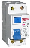
Рисунок 1 – ДTwo-pole RCD with a rated current of 100 A
The main task of the RCD is to protect a person from electric shock and from the occurrence of a fire caused by a current leakage through worn-out insulation of wires and poor-quality connections.
Combined devices combining RCD and overcurrent protection are widely used, such devices are called RCD-D with built-in protection against overcurrents, or simply a different automaton.
All RCDs are classified according to the type of the input signal into several types (Fig. 2). [3]
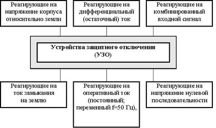
Рисунок 2 – RCD classification by input signal type.
Depending on the characteristics of electrical installations for which RCDs are intended, they are classified according to:
• the neutral mode of the power supply of the electrical installation;
• type and frequency of current;
• voltage; number of phases (poles);
• mobility.
Depending on the neutral mode of the power supply of the electrical installation, the RCDs are divided into devices intended for electrical installations with isolated or with a deadly grounded neutral.
By type and frequency of current, the RCDs are divided into devices intended for electrical installations:
• alternating current of frequency 50 (60) Hz;
• Alternating current of non-industrial frequency;
• direct current; rectified current;
• two or more kinds of current from among the above.
RCDs designed to disconnect electrical installations when a person touches parts that are under voltage are divided into devices designed for electrical installations of the following voltage classes: alternating current frequency 50 (60) Hz - 127, 220, 380, 500, 660, 1140 V; alternating current of frequency 400 Hz - 200 V; (rectified) current is 110, 220, 275, 400 V. The residual current devices intended for switching off the electrical installation when a leakage current develops in it are subdivided into devices designed for the electrical installations of the above-mentioned voltage classes, and also 6000 and 10000 V frequencies of 50 (60) Hz. According to the number of phases (poles), the RCDs are divided into: single-phase (single-pole); two-phase (two-pole); three-phase (three-pole, four-pole).
By types of protection means interacting with the RCD, the devices used with:
• Protective earth;
• With a zeroing;
• automatic short-circuit to the ground of the damaged phase (by shunting the earth leakage current leakage circuit);
• compensation (automatic or static) of the leakage current (earth fault).
The main parameters by which this or that RCD is selected are: rated load current, i.e. operating current of the electrical installation, which flows through normally closed contacts of the RCD in standby mode; The rated voltage (the effective value of the voltage at which the operation of the UZO-220, 380V is ensured); set point (differential tripping current or minimum value of the input signal that triggers the RCD and subsequent automatic shutdown of the damaged section of the network or current collector); time of operation of the device.
The principle of the RCD is based on the measurement of the current balance between the current-carrying conductors entering into it using a differential current transformer. If the current balance is violated, the RCD immediately opens all the contact groups entering into it, thus disabling the faulty load (Fig. 3).
Рисунок 3 – RCD circuit and operating principle.
The RCD measures the algebraic sum of the currents flowing through the controlled conductors (two for a single-phase RCD, four for a three-phase RCD, etc.): in the normal state, the current "flowing in" along one conductor must be equal to the current "flowing" through the others, then is the sum of the currents passing through the RCD is zero (more precisely, the sum should not exceed the allowable value). If the sum exceeds the permissible value, it means that part of the current passes beyond the RCD, that is, the monitored electrical circuit is faulty - there is a leak in it.
In other words, when a person touches open conductive parts or the case of an electrical receiver that, due to a breakdown of the insulation, is under voltage, an additional leakage current ID, which is a differential (differential) current, will flow through the phase conductor through the RCD in addition to the load current I1. The inequality of the currents in the primary windings - I1 + ID in the phase conductor and I2 = I1 in the zero working conductor - causes an unbalance of the magnetic fluxes and, as a consequence, the appearance in the secondary winding of the transformed differential current.
If this current exceeds the preset value of the current of the threshold element of the trigger body 2, the latter operates and acts on the actuator 3. The actuator, consisting of a spring actuator, a trigger and a group of power contacts, opens the electric circuit. As a result, the electrical installation protected by the RCD is de-energized. The time to disable the RCD is on the order of (0.06-0.07) s, which ensures human security. To perform periodic monitoring of the serviceability of the RCD, a test circuit 4 is provided. When the "T" button is pressed, an artificial circuit of the current of the tripping differential current is artificially created. The operation of the RCD in this case means that the device as a whole is OK.
The use of RCDs controlled by a differential current provides a high level of electrical safety. Such RCDs are more efficient than other known devices.
Therefore, the international electrotechnical standards pay more attention to protective measures using RCDs. There is a need for daily intensified works on the introduction of RCDs at enterprises, in residential and public buildings.
In addition, it is necessary to constantly conduct research in search of new solutions in the development of RCDs and new protective systems working together with RCDs. For example, expand the scope of research and application of RCD type HFI with functionally conditional dependence on supply voltage, limiters of voltage peaks based on diamond materials, RCD with power semiconductor elements, RCD with differential high-sensitivity magnetoresistor, new protective systems with RCD TN-CS-Tk, TN -S-Tk, TT-Tk, etc., which in my opinion is promising. [4]
References
- Ф. Штепан «Устройства защитного отключения, управляемые дифференциальным током» /Ф. Штепан Прага, 2000, 90 с; с ил.
- IEC 60947-2:2016. Low-voltage switchgear and control gear. Part 2: Circuit-breakers. Edition 5.0. – Geneva: IEC, 2016-06.
- Носанов Н.И. Устройства защитного отключения и их применение. Учебное пособие для студентов вузов.- Макеевка: ДонНАСА, 2003. –359 с.: ил.
- Электробезопасность. Устройства защитного отключения и их применение / Носанов Н.И., Тимченко В.И., Романова Т.И. – Донецк: Норд-Пресс, 2009. – 84с.
- Ильинов С.С., Степанюк А.Н. Исследование устройств защитного отключения // Научное сообщество студентов XXI столетия. Технические науки: сб. ст. по мат. XXVIII междунар. студ. науч.-практ. конф. № 1(27). URL: http://sibac.info/archive/technic/1(27).pdf