
Abstract
Content
- Introduction
- 1. Theme urgency
- 2. Goal and tasks of the research, the planned results
- 3. A review of literary sources
- Conclusion
- References
Introduction
One of the ways of energy saving in the electric drive is the transition from an unregulated electric drive to an adjustable one. With this transition, energy savings are often achieved through the process that the drive services. Sometimes the energy savings can exceed own consumption of the electric drive. So, moving from the constant speed of the conveyor, which delivers various parts to the quenching furnace, to a flexibly controlled one, it is possible to optimize the thermal process, in particular, according to the energy criterion. It is obvious that the power of processes of slow transportation and hardening differ by several orders of magnitude. Also, in order to obtain useful effects from the transition to a regulated electric drive, changes in the coordinates (speed, torque) of the drive are often needed in very small limits with limited requirements to the quality of regulation. A striking example is a slight change in the speed of the pump supplying hot water to the building, which in turn leads to a saving of hot water [1]. The advantages of an asynchronous squirrel-cage motor in comparison with DC motors, such as high reliability, lower cost, simplicity of manufacture and operation, in combination with high adjusting and dynamic parameters make the asynchronous variable-speed drive into the dominant type of adjustable electric drive, only technological tasks, but also the problem of energy saving [2].
1. Theme urgency
For today the tendency to decrease in power expenses is accurately traced. It is especially relevant for large industrial enterprises, where the main consumers of electric power are electric motors used for various mechanisms. Among the electric drives of industrial mechanisms, it is possible to distinguish a group of turbomechanisms (fans, pumps, compressors), which, as a rule, operate in a long-term mode and consume about 25% of all generated electricity [2]. Due to the sufficiently high installed power of the electric motor and the long operating regime, these units are of particular interest for implementing energy saving measures.
2. Goal and tasks of the research, the planned results
The goal of the master's work is research of the energy characteristics of a regulated electric drive for the fan and determine the most effective methods for improving them.
To achieve this goal, it is necessary to solve the following tasks:
- To study the literature on fan installations and methods of energy saving by means of an electric drive;
- To develop a mathematical model of a fan installation with a frequency-controlled asynchronous electric drive and to confirm its adequacy to a real object;
- Analyze on the basis of research on the mathematical model various methods for improving the energy characteristics of the electric drive fan;
- On the basis of the analysis, determine the most effective energy saving methods for a fan unit with a regulated electric drive;
- Verify the feasibility of the selected energy saving method in the experimental installation.
Planned results:
- Mathematical model of a fan installation with a variable-frequency drive, providing the possibility of studying energy and technological characteristics;
- Recommendations for improving the energy performance of electric fan drives for industrial use;
- Laboratory stand for carrying out experimental research of variable-frequency drive of the fan.
3. A review of literary sources
Fans are called superchargers of rotary type, intended for supplying gases or air with a small head (up to 15 kPa) and gas density ρ=1,2 kg/m3 [3]. The fans are divided into centrifugal and axial fans. Centrifugal fans are classified as follows [4]:
- On the created pressure:
- low pressure (up to 1 kPa);
- medium pressure (up to 3 kPa);
- high pressure (above 3 kPa).
- By appointment:
- general purpose – to move clean air and non–corrosive gases at a temperature of 180 °С and air containing dust in an amount not exceeding 150 mg/m3;
- for technological needs: when moving aggressive media – vinyl plastic; in explosion–proof design – aluminum; for the movement of air contaminated with mechanical impurities – dust;
- smoke exhausters – for moving flue gases.
- In the direction of rotation of the impeller:
- right rotation – if the wheel rotates clockwise;
- left rotation – if the wheel rotates counter–clockwise;
- according to the location of the outlet: upper, right, left, lower;
- by the drive method: on a belt drive or on one shaft with an electric motor.
The description of the fan design and the principle of operation are described in detail in [3].
The most common ways to control the performance of centrifugal fans are [5],[6]:
- Regulation by turning the blades of the guide;
- Regulation of the outlet section of the fan by the gate;
- Regulation by changing the rotational speed of the fan shaft.
In the first case, the capacity is regulated by reducing the cross-section of the inlet channel and twisting the flow at the input to the impeller. This method is simple, but the efficiency of the whole installation will decrease.
The second method involves the installation of a damper (gate) in the output channel of the fan, by means of which the air supply is regulated. This method is also called throttling. Despite the constructive simplicity, the regulation of the gate leads to an increase in the cost of electricity, so this method is the most uneconomical.
The third method involves the use of a variable-frequency drive. By controlling the speed of rotation, it is possible not only to increase or decrease the air supply, but also to maintain the efficiency of the installation constant over the entire control range. To date, this method of regulation is the most efficient in terms of energy costs, but the cost of such an installation will increase.
For turbomechanisms, working at low speeds for a long time can lead to a reduction in energy consumption, eliminate sudden fluctuations in temperature or flow and other system losses associated with the on/off operation of conventional single-speed system [7].
The essence of frequency control is as follows. The speed of rotation of the stator electromagnetic field of three-phase AC motors is proportional to the frequency of the mains, which allows to regulate their speed by smoothly changing the frequency of the mains voltage. This is the most economical way of smoothly adjusting the speed of squirrel-cage induction motors, since the motor works with a small amount of slip of the rotor in the entire control range [8].
The ability to adjust the speed of the asynchronous motors by changing the frequency follows from the expression for the ideal no-load speed:

where f1 – is the frequency of the stator winding voltage; рп – is the number of pairs of motor poles [2].
By varying the frequency f1 of the stator winding voltage, it is possible to obtain different speeds of ideal idling. In this case, the dependence of the ideal idle speed on the frequency of the stator winding voltage is linear. The mechanical characteristics of blood pressure in the frequency method of speed regulation can differ significantly from the natural characteristics. With a constant amplitude of the voltage applied to the stator winding, with a decrease in f1, the starting and crucial torques of the motor increase, and the stiffness of the mechanical characteristics increases. However, at a constant voltage of the power supply U1 with a decrease in the frequency f1 the magnetizing current and the stator current sharply increase. The magnetic system of the engine is saturated. As a result, electrical and magnetic losses increase substantially. To improve the technical and economic performance of the engine with frequency change, it is necessary to adjust the amplitude of the voltage U1 as a function of the frequency f1 and the load torque M [2].
Academician M.P. Kostenko established the following law governing the amplitude and the actual value of the voltage as a function of frequency: in order to ensure an optimal operating mode of the induction motor for all values of frequency and load, the relative voltage of the motor must be changed in proportion to the product of the relative frequency by the square root of the relative motor torque. This law can be written as:
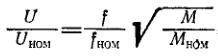
or in relative units:
where γ=U/Uном – relative voltage stator, α=f/fном – relative stator frequency, µ=M/Mном – relative torque.
A detailed description of Kostenko's law can be found in [9].
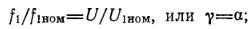
In particular cases we will have the following dependences:
- at a constant nominal torque М=Мном:
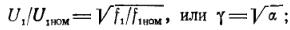
- at constant power (Pн=ωномМном ≈ 2πf1Мном):
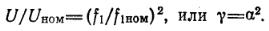
- at a simple fan load:
For each of these cases, you can graphically depict the voltage versus frequency.
Figure 1 – Graphic representation of Kostenko's law
(animation: 6 frames, 10 reiteration cycles, 38,5 kilobytes)
As is known, at U/f-regulation, voltage and current are considered as scalar quantities, i.e. modules of these quantities are used. Therefore U/f-regulation is also called scalar [10]. Such speed control is characteristic in open-loop control systems [2].
The most common type of electrical converters in the market today are frequency converters with an intermediate DC link. Low-power frequency converters are designed according to the scheme Uncontrolled three-phase rectifier – a two-level inverter
, and for large capacities they are built using multilevel inverters or by the principle of a series connection of low-voltage cells.
With a functional diagram of such frequency converters, as well as a detailed description of the elements of the converters, you can see in this source [11].
The most common are frequency converters with a DC link, in which the shape of the stator current, close to a sinusoidal one, is achieved by the use of inverters with pulse-width modulation [10].
The description of the pulse-width modulation and the features of its implementation are given in [11].
Conclusion
- A review of literary sources on the topic of dissertation work showed that adjustable AC drives are increasingly used in fan installations, displacing old systems with mechanical capacity control.
- To ensure high energy performance of the fan unit, it is necessary to use a regulation law appropriate to the nature of the change in the load torque.
- In most cases, for fans, the quadratic law of the dependence of the load moment on the speed of rotation is adopted. At the same time, the aerodynamic characteristics of the fans indicate a different nature of this dependence at different sites.
- The question of the effect of a simplified representation of the mechanical characteristic of the fan mechanism on energy indicators is currently insufficiently studied.
- The solution of the task set in the master's work will provide practical recommendations for the effective use of variable-frequency drives in fan installations.
At the time of writing this abstract of master's work is not yet complete. The estimated date of completion of the master's work: June 2017. The full text of work and materials on the topic can be obtained from the author or his adviser after that date.
References
- Энергосберегающая технология электроснабжения народного хозяйства: В 5 кн.: Практ. пособие/Под ред. В.А. Венникова. Кн. 2. Энергосбережение в электроприводе/Н.Ф. Ильинский, Ю.В. Рожановский, А.О. Горнов. – М.: Высш. шк., 1989 – 127 с., ил.
- Браславский И.Я., Ишматов З.Ш., Поляков В.Н. Энергосберегающий асинхронный электропривод. – Москва, Academa 2004. – 202 с.
- Насосы, компрессоры и вентиляторы. Шлипченко З.С., К.,
Техніка
, 1976, 368 с. - Галдин В.Д. Вентиляторы и компрессоры: учебное пособие. – Омск: Изд-во СибАДИ, 2007. – 105 с.
- Исследование систем управления электроприводами турбомеханизмов [Электронный ресурс] – Режим доступа: http://masters.donntu.ru/2010/etf/kononenko/diss/index.htm, свободный.
- Черкасский В.М. Насосы, вентиляторы, компрессоры: Учебник для теплоэнергетических специальностей вузов. – 2-е изд., перераб. и доп. – М.: Энергоатомиздат, 1984. – 416 с., ил.
- Energy Savings Potential and Opportunities for High-Efficiency Electric Motors in Residential and Commercial Equipment [Электронный ресурс]. – Режим доступа: https://energy.gov/sites/prod..., свободный.
- Онищенко Г.Б., Юньков М.Г. Электропривод турбомеханизмов. М.,
Энергия
, 1972. – 240 с., ил. - Булгаков А.А. Частотное управление асинхронными двигателями. – 3-е перераб. изд. – М.: Энергоиздат, 1982. – 216 с., ил.
- Соколовский Г.Г. Электроприводы переменного тока с частотным регулированием. – Москва, Academa 2006. – 265 с.
- Анучин А.С. Системы управления электроприводов: учебник для вузов – М.: Издательский дом МЭИ, 2015. – 373 с.: ил.