
Abstract
Content
- Introduction
- 1. Theme urgency
- 2. Goal and tasks of the research
- 3. Mobile robot. Classification of mobile robots
- 4. Choice of hardware
- 4.1 L298 Dual H-Bridge driver
- 4.2 Voltage stabilizer LM7805
- 4.3 Voltage stabilizer LF33cv
- 4.4 Bluetooth-module HC-05
- 4.5 Ultrasonic distance sensor HC-SR04
- 4.6 Digital line sensor TCRT5000
- 5. Experimental platform of the mobile robot
- 6. Organization of mobile robot power
- Conclusion
- References
Introduction
Each year, the robotics market scrolls
5-6 billion dollars, and this figure is constantly growing. Apparently, the century of accumulation of knowledge and theoretical science is replaced by a new era - when all sorts of robots and mechanisms fill the world. According to the latest data, 1.8 million of the most diverse robots – industrial, household, robot-toys – are working in the world today. What is a robot?
A robot is an electromechanical, pneumatic, hydraulic device, a program, or a combination of them, working without human intervention and performing the actions usually performed by a person. In other words, a robot is an automatic device that mimics the movements and actions of a person. The robot is built on computer technology, the robot consciousness is a computer with which the information can be read and transferred to a separate medium. The robot is not treated, but is repaired by entering the appropriate diagnostic programs.
The robot lacks associative thinking. He has no curiosity – there is only a program for the accumulation of information that he needs. The robot understands everything with the mind, spiritual qualities are not inherent in him – after all he does not have a soul.
However, today, experts in the field of robotics have about the same difficulties as 30 years ago from computer developers. Due to the lack of common standards and platforms, creators of robots have to start developing each new creation from scratch [1].
1. Theme urgency
Recently, the process of automation of all technical equipment used in machine tools, machines and mechanisms, robotics complexes has become increasingly important. Thanks to the introduction of new technologies in production, labor productivity is significantly increased, and the share of manual labor in comparison with automated labor significantly decreases. The technical level of the products is increasing, and its quality is significantly improved. All this, probably, would not have been possible without microprocessor computing. Devices that are implemented with the use of microprocessors have higher performance in comparison with devices performed on separate logic circuits, and the cost of the former is much smaller.
2. Goal and tasks of the research
The goal of the master's work is to create a structure for a mobile robot and to study the control system of a mobile robot.
Main tasks of the research:
- Drawing up a scheme for managing a mobile robot.
- Selecting a microcontroller.
- Selection of the robot's hardware.
- Analysis of the results.
3. Mobile robot. Classification of mobile robots
Mobile robot – an autonomous system that exists in the physical world, does not have a fixed location, can feel its surroundings, and can influence it to achieve some goals.
In modern robotics robots are defined as a class of technical systems that in their actions reproduce the motor and intellectual functions of a person. From a conventional automatic system, the robot is characterized by a multipurpose designation, great versatility, the ability to restructure to perform a variety of functions.
Robots can be classified by:
- areas of application – industrial (industrial), military (combat, providing), research, medical;
- habitat (operation) – land, underground, surface, underwater, air, space;
- degrees of mobility – stationary, mobile;
- type of control system – software, adaptive, intelligent;
- functional purpose – manipulative, transport, information, combined;
- the level of universality – special, specialized, universal.
Also robots are classified by constructive features:
- type of actuators – electrical, hydraulic, pneumatic;
- type of propulsor – tracked, wheeled, wheel-tracked, semi-tracked, walking, wheel-walking, rotary, with loop, screw, jet and jet propulsors;
- constructive features of technological equipment – by the number of manipulators, by the load-carrying capacity of manipulators, by the coordinate system of the working area (linear, angular);
- type of sources of primary control signals – electrical, bioelectric, acoustic [2].
4. Choice of hardware
As the management object in this course project is the developed mobile robot # WallE Pro. The robot consists of the following sensors and modules: ultrasonic distance sensor HC-SR04, Bluetooth module HC-05, digital line sensor TCRT5000, digital gyro GY-50 L3G4200D, ultrasonic sensor Sonar-EZ1, L298 Dual H-Bridge driver, voltage regulators LF33n and 7805.
4.1 L298 Dual H-Bridge driver
L298n - is a dual bridge driver for controlling bi-directional loads with currents up to 2A and voltage from 4.5 V to 46 V. The chip is designed to control relays, solenoids, DC motors and stepper motors. The L298n has TTL compliant inputs. In L298n, there is a separation of the power supply for the logic circuit and for the load, which allows you to connect a load with a smaller or larger supply voltage than the chip, and also reduces interference.
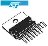
Figure 1 – L298 Dual H-Bridge driver
L298n chips have built-in protection against overheating. The outputs of the microcircuit are switched off when heated to a temperature of about +70°С [3].
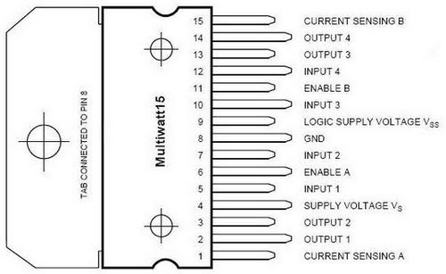
Figure 2 – Pin arrangement L298n
Based on the datasheet to the L298n, a driver card was designed and made. Current sensors are made on one and on the other side of the driver bridge. The board is equipped with LED indication, which shows the direction of the engine.
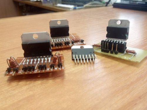
Figure 3 – Driver board L298n
4.2 Voltage stabilizer LM7805
Classical parametric voltage regulator 5V LM7805 in the TO-220 package. Proven time and millions of amateur and professional designs, the stabilizer is indispensable in designs for which not only the voltage stability, but also the minimum noise level of the supply voltage is important. Simple connection and minimum number of additional external components.
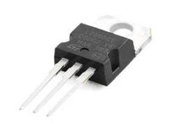
Figure 4 – Voltage stabilizer LM7805
For stable operation of the stabilizer, it is necessary to install at the inlet and outlet of a ceramic and electrolytic capacitor with a capacity of 0.1 μF and 100 μF for a voltage not lower than the voltage of the corresponding circuit.
Stabilizer characteristics:
- Input voltage: 7V to 25V;
- Output voltage: 5V;
- Maximum output current: 1.5A;
- Case: TO-220.
After certain tests of this stabilizer, it became necessary to increase the current by connecting two such stabilizers in parallel, we got twice the output current [4].
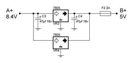
Figure 5 – Connection diagram of stabilizers LM7805
4.3 Voltage stabilizer LF33cv
Voltage stabilizer with fixed output 3.3V. It features high stability and high output current of 800 mA.
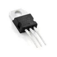
Figure 6 – Voltage stabilizer LF33cv
Stabilizer characteristics:
- Output voltage: 3.3V;
- Output current: 500 mA;
- Maximum input voltage: 16V;
- Voltage drop: 1V (input can not be lower than 3.3 + 1 = 4.3V)
- Integrated current and temperature protection;
- Body: TO-220;
- Manufacturer: STMicroelectronics
After certain tests of this stabilizer, it became necessary to increase the current by connecting two such stabilizers in parallel, we got twice the output current [8].
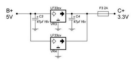
Figure 7 – Connection diagram of stabilizers LF33cv
4.4 Bluetooth-module HC-05
Bluetooth has long and firmly entered our life as a convenient communication protocol for various devices: mobile phones, laptops, PDAs, headsets, mice, keyboards... The list can continue for a long time. Usually this technology is integrated into their products by large electronics manufacturers in the form of a tiny chip in the BGA or QFN case. And what about us, the simple electronic people who do not own the dark forces of creating 4-layer boards and kung fu micromontage? For this, there is Bluetooth-module HC-05 from our chinese colleagues [5].
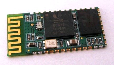
Figure 8 – Bluetooth-module HC-05
4.5 Ultrasonic distance sensor HC-SR04
Using ultrasonic waves, it measures the distance to the object or simply detects an obstacle in the path of movement of the mobile structure. A piezo-radiator of ultrasound and a microphone reflected on the wave are placed on the module board. Unlike infrared distance meters, the ultrasound sensor HC-SR04 is not affected by light sources or the color of the obstacle. There may be difficulties in determining the distance to fluffy or thin objects. We draw attention to the fact that the speed of sound in the air depends on the temperature. This affects the accuracy of the sensor. Typical applications are parking sensors, level controllers, terrain monitoring devices, etc [6].
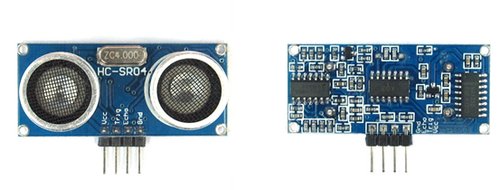
Figure 9 – Ultrasonic distance sensor HC-SR04
4.6 Digital line sensor TCRT5000
The digital line sensor allows you to determine the color of the surface around it. The output is a simple binary digital signal: a logical 0 or 1, depending on the color that it sees before itself. The unit is black or empty, zero is not black [7].
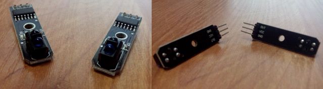
Figure 10 – Digital line sensor TCRT5000
5. Experimental platform of the mobile robot
The basis of the developed robot is the debug board STM32F4. At the first level of the robot (Fig. 12) there are DC motors, two drivers for motor control, a Bluetooth module HC-05, digital line sensors TCRT5000, signal conversion boards, ultrasonic proximity sensors HCSR04, voltage stabilizers LF33cv and LM7805, gyroscope. At the second level (Fig. 13) is the STM32F4 debug board itself and the robot's power supply. The drivers were made with their own hands based on the L298N driver similarity chip. Autonomous power is provided by lithium-ion batteries taken from a laptop. For the safe operation of lithium-ion batteries in view of their explosive safety fuses are provided. In the future, it is planned to replace the robot body and create a new one on a 3D printer.
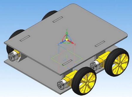
Figure 11 – Approximate view of the robot model
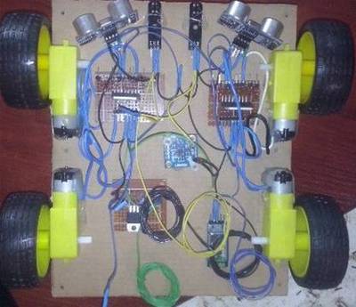
Figure 12 – The first level of the robot
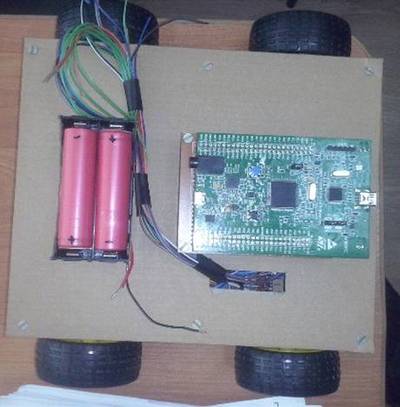
Figure 13 – The second level of the robot
6. Organization of mobile robot power
The mobile robot is powered by rechargeable batteries that were taken from the laptop batteries already used, and a backup battery made of the used IPhone batteries was made.
Recently li-ion is gaining popularity, as it provides the necessary voltage and capacity. In form, it resembles finger
AA and little finger
AAA batteries. The output voltage is 3.7V. Typical capacity: 2200-3000 mAh. AA and AAA batteries have a voltage of 1.5V (AA and AAA –1.2V batteries) [9].
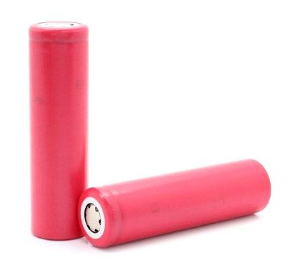
Figure 14 – LI-ION battery type 18650
Most often, the 18650 is a li-ion battery. The advantages include:
- High energy density;
- Low self-discharge;
- Lack of memory effect;
- Ease of maintenance;
- Low specific gravity.
The disadvantages are:
- Li-ion batteries are susceptible to failure during recharging and/or overheating. To solve this problem, all household batteries are equipped with a built-in electronic circuit that does not allow recharging and/or overheating due to charge;
- If the battery is not treated in a safe manner, the batteries may fail more often than other types of batteries. A full charge
kills
the lithium-ion battery. After that, the battery will not be restored; - Optimal storage conditions for Li-ion batteries are achieved with a 40% charge from the battery capacity at a temperature of about 5 degrees Celsius. At the same time, low temperature is a more important factor for small losses of capacity in long-term storage. The average shelf life (service) of a lithium battery is an average of 36 months;
- Another feature of these batteries is aging. Lithium batteries age, even if not used.
18650 is used where a large capacity is required. In our example this is LED lights. In the left lantern the battery AAA is installed, on the average the battery AA, in the right lantern the LED CREE SST-50 is established. To work it needs a lot of power. The 18650 battery is perfect, which is why the flashlight is made for it. Some lanterns are arranged so that instead of the 18650 battery it is possible to install an adapter for 3 AAA batteries. At the same time, the voltage practically coincides: 3.7V and 4.5V (= 1.5V*3). In this case, of course, there is a loss of capacity of the battery. It should also be noted that it is from these elements that laptop batteries are accumulated.
In this case, we use SANYO batteries, we use them in the amount of 2 pieces. Connected in series to the power supply circuit of the drive, resulting in a full charge of ≈ 8.4V.
Power supply for bridge drivers on the L298n platform, we use SANYO batteries, we use them in the amount of 4 pieces. Connected in series to the power supply circuit of the drive, resulting in a full charge of ≈ 16.8V.
Consider this type:
- Model: UR18650A (Power Type);
- Standard capacity: 2250 mAh;
- Minimum capacity: 2150 mAh;
- Standard voltage: 3.7 V (Charging 4.25 V);
- Discharge cutoff voltage: 2.5 V;
- Maximum Charging Current: 2.15A;
- Maximum discharge current: 5A;
- Size: 18.6*64.9;
- Weight: 44g.
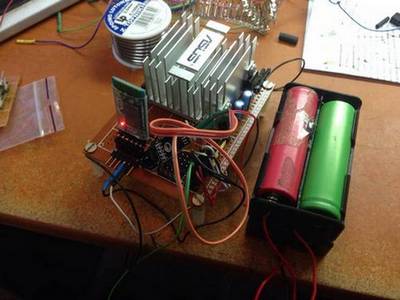
Figure 15 – The appearance of the power supply by this mobile robot
The subject of developing mobile robots was started in the bachelor's degree. A video review of the bachelor's work is presented below:
Figure 16 – Work of the mobile robot (animation: 6 frames, 150 kilobytes, 10 reiteration cycles)
Conclusion
Based on the work done, it is planned:
- Print the platform on a 3D printer.
- Installation of additional ultrasonic distance sensors HC-SR04 for automatic parking.
- Complete debugging of all sensors.
- Installation of additional transistors to disconnect sensors for energy saving purposes.
At the time of writing this abstract of master's work is not yet complete. The estimated date of completion of the master's work: June 2018. The full text of work and materials on the topic can be obtained from the author or his adviser after that date.
References
- Что такое мобильный робот? // GENERATION [Электронный ресурс]. – Режим доступа: http://ed.generation.kz/256..., свободный.
- Классификация мобильных роботов // helpiks.org [Электронный ресурс]. – Режим доступа: http://helpiks.org/6-11883.html, свободный.
- Dual full-bridge drive L298N // tech.dmu.ac.uk [Электронный ресурс]. – Режим доступа: http://www.tech.dmu.ac.uk/..., свободный.
- Voltage Regulator LM7806 // fairchildsemi.com [Электронный ресурс]. – Режим доступа: https://www.fairchildsemi.com/..., свободный.
- HC-05 Bluetooth to Serial Port Module // robotshop.com [Электронный ресурс]. – Режим доступа: http://www.robotshop.com/..., свободный.
- HC-SR04 Datasheet // electroschematics.com [Электронный ресурс]. – Режим доступа: http://www.electroschematics.com/..., свободный.
- TCRT5000 Datasheet // alldatasheet.com [Электронный ресурс]. – Режим доступа: http://www.alldatasheet.com/..., свободный.
- Voltage Regulators LF33CV // elcodis.com [Электронный ресурс]. – Режим доступа: http://elcodis.com/..., свободный.
- LI-ION аккумулятор типа 18650 // aliexpress.com [Электронный ресурс]. – Режим доступа: https://ru.aliexpress.com/....