
Synthesis of a discrete system of regulation for the fution damping of elastic vibrations in multi-mass systems
Сontents
- Introduction
- 1. Description of the control object
- 2. Synthesis of the control system
- Conclusions
- Sources used
Introduction
In modern systems, multimass models are increasingly used. This will ted conducts s camping on the model transfer mechanism of the bridge of the bridge crane with the purpose of quenching occurring due to elastic vibration of the bridge length, which lead to considerable trouble when working with such a mechanism. It can be such unpleasant phenomena as rocking the crane moving cargo, which can worsen the production process and lead to a drop in the productivity of the device. Another important aspect is that in this work, the resulting elastic fluctuations gradually lead to fatigue of the material and as a consequence the early failure of the entire mechanism and thus entail a halt of the entire production process for the time of crane repair. In this paper, a synthesis of the control system will be carried out, which could eliminate elastic fluctuations. To control this system will be used state-feedback controller. The peculiarity of the state-feedback controller is that for operation it needs the entire state vector of the controlled system, but in view of the fact that it is directly from the control object. Often, we can not get all the system state variables needed to operate the state-feedback controller in view of the fact that quite often these values can not be directly obtained with the help of sensors, since they can be difficult or even immeasurable. Basically from the object we can get a minimum of such variables. For example, the speed of any links and the current in the circuit, the voltage applied to the engine and the angle of rotation of the motor shaft. To obtain the remaining state variables, it is necessary to use the system state observer, which will be synthesized on the basis of the mathematical model of the object and be able to give all the system state vector necessary for the operation of the state-feedback controller. However, the signal received from real sensors very often enters the control system very noisy and thus can disrupt the operation of the entire system. In order to avoid such malfunctions of the system due to the noise from the sensors, it is necessary to use a filter that would eliminate the signal from noise. As such a filter can serve as a Kalman filter, which is a very powerful tool, it can not only filter the signal received from the sensors, based on the mathematical model it can provide the entire state vector of the system. Thus, using these two powerful tools together, we can implement the control system without the use of an outside observer and at the same time obtain the most possible reliable filtered readings of the sensors. Also in this paper we tested the obtained model at various discreteness levels of the control system and made conclusions about the efficiency of the Kalman filter under these changes.
1. Description of the control object
The control mechanism was the mechanism of moving the bridge of the bridge crane.
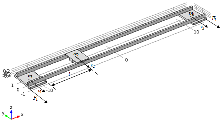
Figure 1 – Сontrol object
In order to simplify our model and the bridge represented as two m-metal profile with rectangular cross-section and too low values of density and modulus of elasticity of the material so that the design mass corresponded approximately to the real data. The trolley in this case will be fixed in one position and will be modeled as an integral part of the bridge design. Next, let's move the trolley to middle gantry and is applicable to the outermost portion of our design effort, which corresponds to a rate acceleration bridge to 0.5 m/s for 1 s at working speed variation law trapezoidal. [3]
Graphs change rates s of extreme points of the bridge and trolley v1 v2, which occurs at its middle point, shown in Fig.2. These graphs clearly show that the considered points of the construction perform undamped fluctuations, which gradually reduce its strength and, in consequence, can cause the crane to exit from work and personnel injuries.
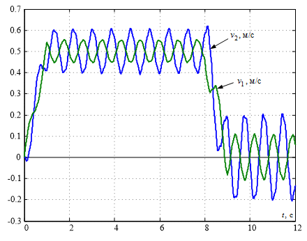
Figure 2 – Graph of transient processes of movement velocities of an elastic bridge crane structure
In order to sepress these undamped oscillations necessary to synthesize the corresponding gantry speed control system that requires linear mathematical model of the controlled object.
In our case, the mathematical model of the object can be compiled on the basis of the kinematic schemes of the multimass systems shown in Fig.3.
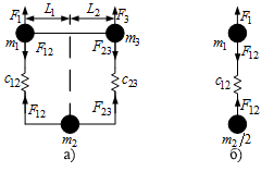
Figure 3 – Kinematic model of the bridge
In Fig.3а the bridge is conditionally represented in the form of three concentrated masses - the extreme points m1 and m3, connected by elastic coupling with the stiffness coefficients from 12 and from 23 to the point m2 in which the trolley is located.
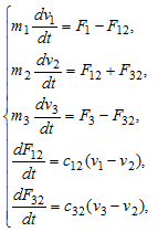
If we arrange the trolley right in the middle of the bridge (L1 = L2), then the stiffness coefficients of the elastic coupling should also be the same. If in this arrangement the elements are equal to each other and the masses that are concentrated at the ends of the bridge, as well as the forces applied to them, at the same distance from the supports whose masses are equal, the kinematic diagram of our control object can be simplified to a two-mass one, leaving one support and a central a point whose mass should be reduced by a factor of 2. The kinematic scheme for such a case is shown in Fig.3b. Its mathematical description will look like this :
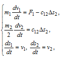
where F1 - force applied to the first mass, F12 - elastic force, Δs2=s1-s2 - is the value of elastic deformation.
If we know the values of the concentrated masses and the time constant of the elastic oscillations of the two - mass system T12=1/2/pi/f, then we can calculate the stiffness coefficient: [3]
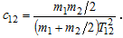
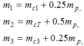
Where:
Thus, having introduced some assumptions and simplifications, we transformed a complex three-mass kinematic system into a simpler two - mass model, on which it would be much easier to carry out experiments and implement a control system with the aim of extinguishing the elastic vibrations that are harmful to the object.
2. Synthesis of the control system
One way to eliminate these oscillations is to use the state-feedback controller. In order to synthesize this controller it is necessary to transform our system into a state space, for this it is necessary to transform the data of the equation into the matrices of the state space:
The vector of input signals is:

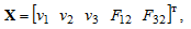
Vector of state variables:
The matrix of state A is equal to:
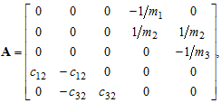
The input matrix B is equal to:
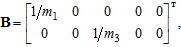
In the Simulink package, a model was synthesized that included a control object in the state space, a state-feedback controller, and a Kalman filter (Figure 6)
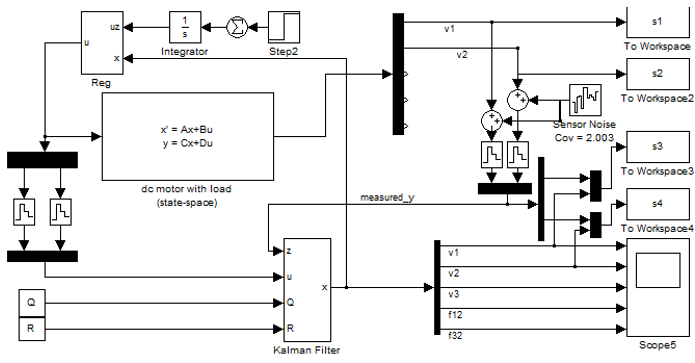
Figure 4 – Test model
On this model are located such elements as the model of the object in the state space, which is based on the matrices of the state of our control object (state-space), the state-feedback controller (Reg) implemented as a negative feedback on the state vector of the object which is obtained from the output of the Kalman filter (Kalman Filter), the input of which is fed noisy speed signals from the control object, as well as control action as well as to the control object, but with a level descriptor to simulate a discrete control system. Also, blocks of sampling and outputting data to the Matlab workspace for obtaining transient graphs. You can also see the block Step and Integrator performing the function of defining the trapezoidal control law.
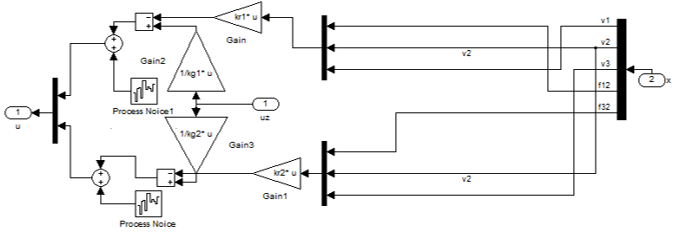
Figure 5 – Reg Content
In the Reg block, there are objects such as feedback factors that are a state-feedback controller and Process Noise blocks that introduce an error into the control system, which does not express the accuracy of the object model description, which in the general case can not be calculated, but can be selected by achieving the best possible results.
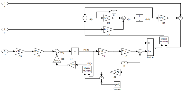
Figure 6 – Content of the block Kalman Filter
Figure 6 shows the contents of the Kalman filter, where signals are input to the input, such as control, noisy signals taken from the control object and noisy, in order to simulate the operation of a real sensor, and the values that characterize the covariance of the sensor and system noise are supplied to the filter input. Covariance of the sensor can be obtained by experimenting by sampling a signal from a real sensor. Covariance of the model can not be obtained in this way and is selected manually.
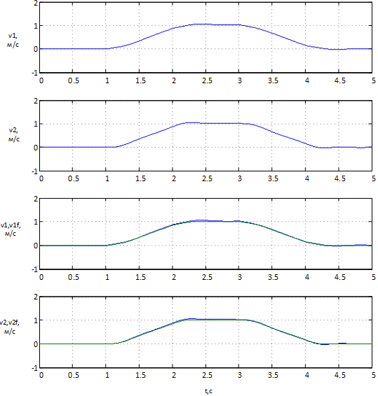
Figure 7 – Simulation results without noise
Figure 7 shows the velocity of the tap points obtained from the control object and obtained from the Kalman filter, the graphs clearly show that the graphs coincide with the minimum error. This means that the Kalman filter works well as an observer of the system and provides an acceptable level of error.
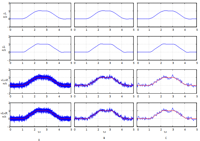
Figure 8 – The results of working with noise at different levels of discrete filter: A) Ts = 0.001s, B) Ts = 0.01s, C) Ts = 0.05s
Figure 9 shows the graphs obtained when the feedback signal received from the control object is noisy. The graphs show the signal received by the filter at various levels of discreteness. It can be noted that with decreasing discreteness within the given limits, the filtering results do not deteriorate, and the system works stably. It can also be concluded that even with such a strong noisy signal, the filter copes with its task giving the system as a whole good performance.
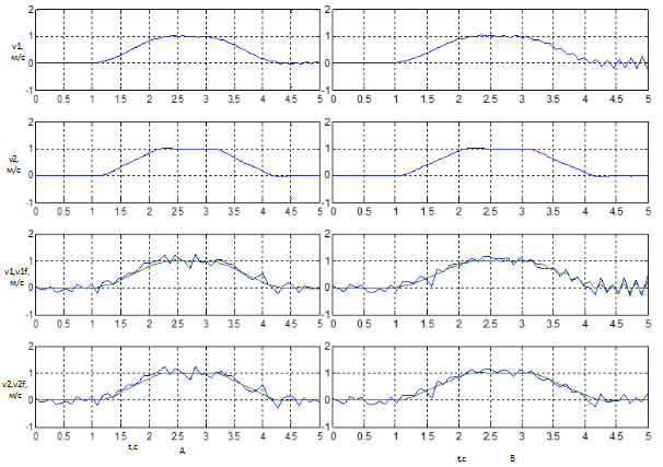
Figure 9 –The results of working with noise at different levels of discrete filter: А) Ts=0.009c, B) Ts=0.091c
If you reduce the discreteness of the system to tenths of a second (Fig. 9), you can see how the filter stops working correctly, and the entire system becomes uncontrollable.
Conclusions
From which it can be concluded that the Kalman filter works well at different sampling rates and can be used on weak controllers, but when the frequency is lowered to critically low values, it is possible to remove the filter from the work thereby violating the entire system and disabling it.
Further work will consist in the further application of this system to a real object, namely, the layout of a bridge crane.
When writing this essay, the master's work is not yet complete. Final completion: June 2018. The full text of the work and materials on the topic can be obtained from the author or his supervisor after the specified date.
Bibliography
- Модальное управление [Электронный ресурс]. – Режим доступа: https://studopedia.ru..., свободный.
- Фильтр Калмана [Электронный ресурс]. – Режим доступа: https://ru.wikipedia.org/wiki/Фильтр_Калмана, свободный.
- Толочко О.И., Палис Ф., Бажутин Д.В. Гашение горизонтальных упругих колебаний конструкции мостового крана / О.И. Толочко, Ф. Палис, Д.В. Бажутин // Електромеханічні і енергозберігаючі системи. Тематичний випуск
Проблеми автоматизованого електропривода. Теорія і практика
- Кременчук: КрНУ, 2012. – Вип. 3/2012 (19). – С. 336-339. - Палис Ф, Толочко О.И., Бажутин Д.В. Анализ поперечных колебаний мостового крана при изменении положения тележки / Ф. Палис, О.И. Толочко, Д.В. Бажутин // Вісник Національного технічного університету
Харківський політехнічний інститут
. – Харків: НТУХПІ
, 2013, №36 (1009). – С. 36-39. - Борцов Ю.А., Соколовский Г.Г. Автоматизированный электропривод с упругими связями. – СПб.: Энергоатомиздат, 1992. – 288 с.
- Макурин А. В., Морозов Д. И. Динамика продольного перемещения мостового крана с учетом упругости элементов конструкции // Электротехнические и компьютерные системы. – 2011. – № 3 (79). – С. 167–169.
- Бажутин Д. В. Моделирование упругих колебаний конструкций крановых установок в пакете Comsol Multiphysics. Научные работы ВНТУ, 2013, № 4