
Abstract
Content
- Introduction
- 1. Relevance of the topic
- 2. Development of the hardware of the laboratory stand
- 3. Methods for calculating the angle of rotation and speed
- Conclusion
- References
Introduction
This work is devoted to the study of a microprocessor control system for regulating the mechanical coordinates of a DC motor. A special feature of the work is the study of the fundamentals of engine control using a laboratory stand based on the STM32F4 debug board.
The stand is a revision of the bachelor project on work with the incremental position sensor.
The task is to acquire skills in collecting and processing scientific and technical information. This is important skill for future professionals working on the manafacture with drives.
1. Relevance of the topic
The relevance of this work is that this development was assembled exclusively for educational purposes, for the preparation of students of the specialty Electromechanical Automation Systems and Electric Drives
,
since It is important to understand and use the information of the most commonly used – pulse incremental position sensor.
2. Development of the hardware of the laboratory stand
The sensor consists of a movable part connected to the measurement object and a fixed part, relative to which the position measurement takes place. The moving part of the sensor is a disk with bar-marks, applied uniformly along the entire circumference [5]. The number of labels determines the main parameter of the sensor or its resolution in marks per revolution Z. The stationary part contains two light emitters and two light receivers, which are two optocouplers. A disc with labels placed between the emitters and receivers in the way that when it rotates at the outputs of the light detectors, two signals in the form of a meander. The placement of optocouplers with respect to each other is performed in such a way that the meanders are displaced relative to each other by 90°.
3. Methods for calculating the angle of rotation and speed
There are sensors from several tens to millions of marks per revolution [5].
It should be noted that for sensors per million marks on revolution, a glass disk does not contain the same million marks.
It is cut into several thousand marks, and the signal coming from the optocoupler is processed as an analog signal.
This signal is similar to the sine and cosine, it is passed through the ADC, and then another 1000 virtual
labels are created inside one sinus period (or one physical label) that the consumer sees at the sensor output.
For one revolution of the sensor, channel A will send Z pulses, and Z pulses will also flow through channel B. These pulses can be counted using a quadrature decoding scheme, and from the phase shift between the signals A and B, calculate the direction of rotation.
In addition to the number of tags per revolution in the passport data of the sensors is usually given the parameter K – the number of pulses per revolution:

The parameter shows how many counting pulses will be received from the quadrature decoder circuit on one revolution. The number of pulses in four times higher, since the circuit distinguishes the edges of the signals A and B, which have 4 sensors per sensor label.
The quadrature position sensor is connected to the inputs of the quadrature decoder of the microcontroller – CAP1/QEP1 and CAP2/QEP2, which can function not only in the quadrature decoding mode, but in the event capture mode. The principle of operation of the quadrature decoder is shown in Figure 1, where it is shown that the timer value, in fact, determines the current position of the rotor. More difficult is the problem of measuring the angular velocity of rotation.
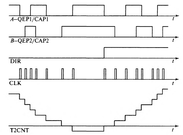
Figure 1 – A-QEP1/CAP1 – channel quadrature A; B-QEP2/CAP2 – channel quadrature В; DIR – directions timer count signal; CLK – clock signal; T2CNT – timer count value.
To measure speed, two methods are usually used:
- Measurement of the number of pulses per time interval
- Measurement of the transit time of a given number of pulses
The first method is the simplest in implementation, but has a significant drawback associated with the fact that pulses from the quadrature decoder must pass a lot during the speed measurement to ensure the required accuracy of the result. So counting, for example, five pulses, you can not say for sure that the impulses were five. After all, during this time, it can pass as 5.1, and 5.9 real label sectors, i.e. the error will be about 20%. Hence it can be concluded that the method is best not to be used in practice.
The second method is more difficult to implement, but there are no shortcomings in the first method. The number of pulses in this method is a quantity known exactly. The pulse packet transit time can be measured by modern microprocessor means to within the inverse of the processor clock speed, which for most modern DSP microcontrollers of the Motor Control family ranges from 25 to 6.67 ns.
We can say that all the values necessary for calculating the speed are found exactly:
Before considering the construction of a speed measurement system, it is necessary to clarify what errors the quadrature position sensor has. During the measurement it is necessary to set the length of the pulse packet, perceived as the measuring path. It is clear that for small-speed measurements it is more reasonable to choose small increments of the path, but there are limiting factors that do not allow you to specify an increment of less than four paths, and all increments not multiples of four.
First of all, this is due to the fact that the marks applied to the sensor glass disk can be of unequal width with transparent areas.
This unevenness makes it impossible to set the increment of the path equal to one (1
), since it can be seen from Figure 1, that the paths of the active and inactive states are different.
From this it can be concluded that the way in which time measurements are carried out must be a multiple of two (2
), because only in this case the path from the label to the label will be the same.
The second kind of sensor error is due to the fact that the phase between the signals A and B is not always 90°, and in the passport data of the sensors, for example, the SKB IS ISL allows a deviation up to ±15°, which may be unstable on the reverse.
Thus, the minimum possible path that can be measured turns out to be equal to four (4
) – four sensor pulses or one mark.
To measure the speed, you must set the path, measure the travel time of the specified path and, dividing the path by time, calculate the speed. Obviously, the smaller the path (in the limit of four pulses) is chosen, the higher the bandwidth of the speed meter. However, with small increments of position at high speeds, the error in measuring time increases. If time is measured with an accuracy of 6.67 ns in modern microcontrollers with a frequency of 150 MHz, then the accuracy of measuring time in four decimal places can be obtained in 66.7 mcs, i.e. the travel time of a path of four pulses or one mark must not be less.
Conclusion
In the process of writing a review on the topic Research of microprocessor based control system for mechanical coordinates tracking of a DC motor
the direct current motors of the type 775 DC motor, driver L298n and debug board STM32F4.
We studied ways of calculating the rotation angle, and the principle of the controlled electric drive.
Appearance of the stand, and demonstration of his work
At the time of writing this essay, the master's work is not yet complete. Approximate date of completion of the master's work: May 2018. The full text of the work and materials on the topic can be obtained from the author or his supervisor after the specified date.
References
- STM32F4 Discovery Datasheet [Электронный ресурс] – Режим доступа: http://www.st.com/content/st_com/en/products/evaluation-tools/product-evaluation-tools/mcu-eval-tools/stm32-mcu-eval-tools/stm32-mcu-discovery-kits/stm32f4discovery.html
- L298N Datasheet (PDF) – STMicroelectronics [Электронный ресурс] – Режим доступа: http://html.alldatasheet.com/html-pdf/22440/STMICROELECTRONICS/L298N/1619/1/L298N.html
- Arduino Uno Datasheet [Электронный ресурс] – Режим доступа: http://arduino.ru/Hardware/ArduinoBoardUno
- TB6612FNG Datasheet [Электронный ресурс] – Режим доступа: http://html.alldatasheet.com/html-pdf/807693/TOSHIBA/TB6612FNG/296/1/TB6612FNG.html
- Анучин А.С. Системы управления электроприводов: учебник для вузов. – М.: Издательский дом МЭИ, 2015. &ndash c.373 137-140.
- 775 DC Motor Datasheet [Электронный ресурс] – Режим доступа: http://www.dsdmotor.com/ProductShow.asp?ID=271
- RS-555 Datasheet [Электронный ресурс] – Режим доступа: https://www.robotshop.com/en/rs-555-12v-6100-rpm-brushed-dc-motor.html
- RS-550 Datasheet [Электронный ресурс] – Режим доступа: http://www.robotstorehk.com/rs_550pcvc.pdf
- 390 DC motor Datasheet [Электронный ресурс] – Режим доступа: https://www.robotshop.com/forum/data-sheets-for-mabuchi-rs-390-and-rs-395-dc-motors-t12037