Introduction
Electrical drives represent a dominant source of mechanical power in various applications in production, material handling, and process industries. Applying the feedback control techniques to electrical drives substantially improves their performance in terms of achieving precise and fast motion control (servo-control) with a high efficiency. Traditionally, the controlled electrical drives were based on directcurrent (DC) motors and analog controllers. However, the rapid development of power electronics and microprocessor technology in the last three decades has propelled application of servo-control to brush-less, alternating-current (AC) drives, and provided implementation of advanced motion control algorithms including compensation of transmission compliance, friction, and backlash effects. The overall control performance, efficiency, reliability, and availability of the controlled electrical drives have been substantially improved, thus accelerating their penetration into various engineering applications
This article presents an overview of controlled electrical drive technology with emphasis on control system design. The presentation is based on the separately-excited DC motor, since control of this motor can be easily understood and readily extended to AC motors. First, the elements of a controlled electrical drive are described (Section 2), which include DC motor and its mathematical model, electronic power converters, sensors, and electronic control units including the basic control algorithms. Next, the steady-state form of DC motor model is used to describe the motor speed adjustment (or open-loop control) in the regions below and above the rated speed, as well as the controlled starting and regenerative braking of the motor (Section 3). This serves as a basis for presenting a cascade structure of motor feedback control, including optimal tuning of current, speed, and position controllers (Section 4). For tracking applications, the feedback system is extended by feedforward paths or a feedforward compensator, in order to reduce the dynamic tracking error (Section 5). Section 6 shows, on an example of permanent-magnet synchronous motor (PMSM), how the naturally decoupled armature and field control of DC motor can be applied to the coupled dynamics of three-phase AC motors. Finally, Section 7 analyzes influences of transmission insufficiencies related to compliance, friction and backlash effects on the static and dynamic behavior of a servodrive, and presents control algorithms for compensating these effects. The theoretical discussions are illustrated by a number of computer simulation results.
2. Elements of Controlled Electrical Drive
Figure 1 shows the structural block diagram of a controlled electrical drive. An electrical motor is coupled to a working mechanism in order to provide a transfer of mechanical power. The main additional features of controlled electrical drives compared to their conventional counterparts are: (i) the power transfer is made time variant/controllable using an electronic power converter , and (ii) the drive motion can be controlled in a precise manner based on the use of feedback paths containing sensors and electronic control unit.
The control tasks can be different, starting from current control (corresponding to openloop torque/force control), through speed and position control, and towards force control. Normally, the controlled power flows from the electrical grid to the working mechanism. However, during transients or occasional continuous braking intervals, the motor switches to a generator mode and the power flows back to the grid. If the power converter does not support the regenerative braking feature (typically in low-power drives), the braking power is dissipated on a braking resistor
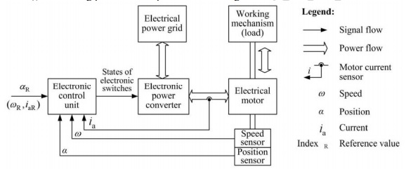
Figure 1 – Structural block diagram of controlled electrical drive.
2.1 Separately-Exited DC Motor
Direct-current (DC) motor (see cross-section schematic in Figure 2a) consists of a magnetic field flux (excitation) circuit (placed on the stator), armature circuit (placed on the rotor), and a commutator which inverts the current in an armature coil whenever it passes through the neutral zone that is perpendicular to the stator field axis. The power is transferred to the armature through brushes that are fixed in the neutral zone and leaned to the commutator.
The excitation and armature circuits can be connected separately from each other, or a series or parallel connection can be utilized instead. The separately-excited DC motors are mostly used in controlled drives, owing to the possibility of independent field and armature current control and related superior control features in a wide speed range.
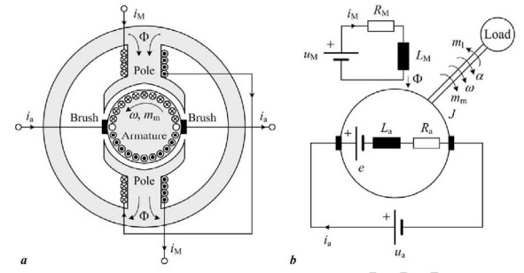
Figure 2 – Simplified cross-section schematic (a) and equivalent scheme of separatelyexcited DC motor.
2.1.1 Dynamic Model
Figure 2b shows an equivalent scheme of the separately-excited DC motor. The stator magnetic flux ? acts upon the armature current ia , thus producing the motor torque. On the other hand, when the rotor rotates, the voltage e (back electromotive force, EMF) is induced in the armature winding. The motor dynamics are described by the following set of differential equations (see Nomenclature), given in both time (t ) and Laplace (s) domain:
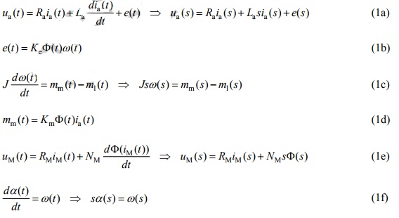
where ?(iM) is the nonlinear static magnetizing curve. The armature circuit, Eq.(1a), can be described by the following transfer function

where Ka=1/Ra and Ta=La/Ra are the armature gain and armature time constant, respectively. Based on Eqs. (1) and (2), a block diagram of the motor model can be created, as shown in Figure 3a. In the basic case of constant excitation circuit voltage (uM = const.?? = const.) or permanent-magnet excitation, the block diagram reduces to the one shown in Figure 3b based on the following substitutions: Kt=Km? and Kv=Ke?.
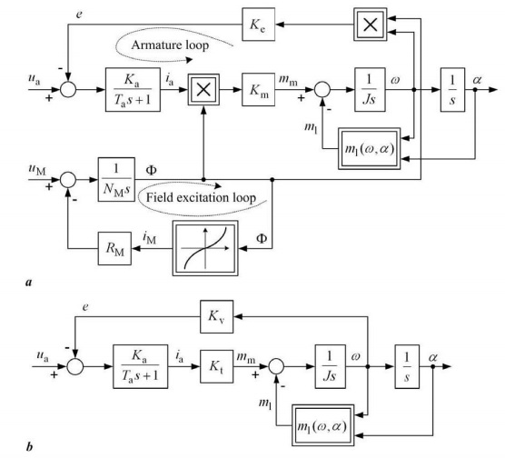
Figure 3 – Block diagram of DC motor: (a) general case and (b) constant-flux case.
Bibliography
1. Armstrong-Helouvry B., Dupont P., Canudas de Wit C. (1994). A Survey of Models, Analysis Tools and
Compensation Methods for the Control of Machines with Friction, 30 (7), 1083-1138. [This survey paper
gives a comprehensive overview of friction effects, appropriate static and dynamic friction models, and
different methods of analysis and compensation of friction effects.]
2. Astrom K.J., Wittenmark B. (1984). Computer Controlled Systems, 446 pp., Prentice-Hall, London, UK.
[This book gives a comprehensive presentation of the field of digital control systems design.]
3. Blaschke F. (1965). Das Kriterium der Doppelverhaltnisse, Technischer Bericht Nr. 9331, Siemens,
Germany. [This report introduces the analytical criterion of damping optimum and its application to
electrical drives control system design.]
4. Bose B.K. (1986). Power Electronics and AC Drives, Prentice Hall, Englewood Cliffs, N.J., USA.
[Presents the basics of electrical power conversion and AC electrical machine control by means of
electronic power converters based on semiconductor switching devices.]