Abstract
In an industry a considerable portion of investment is being made for machinery installation. So in this project we have a proposed a machine which can perform operations like drilling, sawing, shaping (grinding) some lathe operations at different working centers simultaneously which implies that industrialist have not to pay for machine performing above tasks individually for operating operation simultaneously. This paper presents the concept of Multi-Function Operating Machine mainly carried out for production based industries. We have developed a conceptual model of a machine which would be capable of performing different operations simultaneously and is also economically efficient. In this machine we are actually giving drive to the main shaft to which scotch yoke mechanism is directly attached, scotch yoke mechanism is used for sawing operation. On the main shaft a bevel gear system is used for power transmission at two locations.
I. INTRODUCTION
Multi-operation machine as a research area is motivated by questions that arise in industrial Manufacturing, production planning, and computer control. Consider a large automotive garage with specialized shops. A car may require the following work like replace exhaust system, align wheels and tune up. These three tasks may be carried out in any order. However, since the exhaust system, alignment and tune-up shops are in different buildings, it is impossible to perform two tasks for a car simultaneously. When there are many cars requiring services at the three shops, it is desirable to construct a service schedule that takes the least amount of total time.Industries are basically meant for Production of useful goods and services at low production cost, machinery cost and low inventory cost. Today in this world every task have been made quicker and fast due to technology advancement but this advancement also demands huge investments and expenditure. Every industry desires to make high productivity rate maintaining the quality and standard of the product at low average cost. In an industry a considerable portion of investment is being made for machinery installation. So in this project work is proposed where a machine is designed which can perform operations like drilling, sawing, shaping, some lathe operations at different working centers simultaneously which implies that industrialist will not have to pay for machine performing above tasks individually for operating operation simultaneously. Economics of manufacturing: According to some economists, manufacturing is a wealth-producing sector of an economy, whereas a service sector tends to be wealth-consuming. Emerging technologies have provided some new growth in advanced manufacturing employment opportunities in the Manufacturing Belt inthe United States. Manufacturing provides important material support for national infrastructure and for national defense.
Before starting our work we have undergone through many research papers which indicates that for a production based industries machine installation is a tricky task as many factor being associated with it such as powerconsumption (electricity bill per machine), maintenance cost, no of units produced per machine i.e. capacity of machine, time consumption and many more.
Advantages
Multi operations can be performed at the same time.
Power saving as it is manually operated.
Size is compact therefore it requires less space.
Time saving.
Less man power is required.
Low manufacturing & maintenance cost.
Easy machinery used.
Fewer moving parts
Smoother operation
Disadvantages:
it’s totally manually operated.
Time consuming as compared to electrical power.
Without human effort it’s not operated.
Not fit for heavy production.
Rapid wear of the slot in the yoke caused by sliding friction and high contact pressures.
Lesser percentage of the time spent at bottom dead center reducing blow down time for two stroke engines, when compared with a conventional piston and crank shaft mechanism.
Functional Description:
The functional description of the project work is explained in brief here. For better understanding, the total project work is divided into various blocks and each block explanation is provided here. The following is the description of overall function of the module. In this project generally the power is applied to the shaft on which a bevel gear is mounted on it and a second bevel gear at a right angle to it has been mounted on a drill shaft towhich a drill bit is being attached. At one end of the shaft, power is applied manually and other end is being joined to a circular disc, through this circular disc scotch yoke mechanism is being performed (rotator y motion is converted to reciprocating motion). Also in between these two, a helical gear is mounted which transfer its motion to other helical gear which is mounted on a shaft consist of grinding wheel.
II. WORKING PRINCIPLE
There are only two major principles on which this proposed model generally works. They are:
1) Scotch-Yoke mechanism
2) Power transmission through gears.
3) Bevel gears
Scotch Yoke Mechanism:
The Scotch yoke is a mechanism for converting the linear motion of a slider into rotational motion or vice-versa. The piston or other reciprocating part is directly coupled to a sliding yoke with a slot that engages a pin on the rotating part. The shape of the motion of the piston is a pure sine wave over time given a constant rotational speed.

The scotch yoke mechanism is constructed with iron bars. Here the crank is made of wood in some length and the yoke is made of iron. It is noted that the minimum length of the yoke should be double the length of the crank. The crank and yoke is connected with a pin. Iron bars are welded to both sides of the yoke to get the reciprocating motion. The yoke with the iron bars is fixed on the display board with the help of square pipe that is a bit bigger than that of the iron bars. Now the crank is connected through a screw mechanism to the end of the shaft of the bevel gear mechanism. Now the pin on the crank is connected to the yoke. The pin used to connect yoke and crankis a bolt.
Bevel gears are gears where the axes of the two shafts intersect and the tooth-bearing faces of the gears themselves are conically shaped. Bevel gears are most often mounted on shafts that are 90 degrees apart, but can be designed to work at other angles as well. The pitch surface of a gear is the imaginary toothless surface that you would have by averaging out the peaks and valleys of the individual teeth. The pitch surface of an ordinary gear is the shape of a cylinder. The pitch angle of a gear is the angle between the face of the pitch surface and the axis. More description about gears and their drive mechanisms is provided in the further chapters.
The working medium adopted is Mechanical power.
The machine work without the help of electricity.
The Rotary motion of drilling operation performed is also used for performing other tasks like cutting and grinding simultaneously.
The work pieces are to be clamped on the work table using suitable clamping device like vice for the three operations.
After machining the work pieces are to be removed and cleaned.
III. COMPONENTS OF THE MACHINE
1) Frame
2) Scotch Yoke mechanism
3) Bevel gear
4) Bearing (Ball)
5) Rocker arm
6) Hacksaw blade
7) Tool post
8) Drilling chuck
9) Drill tool
10) Single cutting tool
11) Nut and Bolt
12) Other components
Operations Performed By the Machine:
1) Drilling
2) Cutting
3) Shaping
Operations Performed By the Machine:
Drilling
Drilling machine can be defined as an instrument which is used to drill holes. Drilling machine plays an important role in mechanical workshops. The purpose of this project work is to get hold of complete information pertainingto drilling machines. A drilling machine comes in many shapes and sizes, from small hand-held power drills to bench mounted and finally floor-mounted models. Today the Industrial growth is purely depends up on latest machines; therefore the subject of drilling machines is extended too widely, because today wide varieties of drilling machines are designed for various applications. The most advanced version-drilling machine is CNC (Computer Numeric Control); it is used for drilling the PCB’s (Printed circuit boards). CNC Drilling is commonly implemented for mass production.
The machine used for drilling is called drilling machine. The drilling operation can also be accomplished in lathe, in which the drill is held in tail stock and the work is held by the chuck. The most common drill used is the twist drill. It is the simplest and accurate machine used in production industries. The work piece is held stationary i.e., clamped in position and the drill rotates to make a hole.
Cutting:
A hacksaw is a fine-tooth hand saw with a blade held under tension in a frame, used for cutting materials such as metal or plastics. Hand-held hacksaws consist of a metal arch with a handle, usually a pistol grip, with pins for attaching a narrow disposable blade. A screw or other mechanism is used to put the thin blade under tension. The blade can be mounted with the teeth facing toward or away from the handle, resulting in cutting action on either the push or pull stroke. On the push stroke, the arch will flex slightly, decreasing the tension on the blade, often resulting in an increased tendency of the blade to buckle and crack. Cutting on the pull stroke increases the blade tension and will result in greater control of the cut and longer blade life.
Shaping:
The shaping machine is used to grind flat metal surfaces especially where a large amount of metal has to be removed. Other machines such as milling machines are much more expensive and are more suited to removing smalleramounts of metal, very accurately. A shaper is a type of machine tool that uses linear relative motion between the work piece and a single-point cutting tool to machine a linear tool path. Its cut is analogous to that of a lathe, except that it is (archetypal) linear instead of helical. (Adding axes of motion can yield helical tool paths, as also done in helical planning.) A shaper is analogous to a plane, but smaller, and with the cutter riding a ram tha moves above a stationary work piece, rather than the entire work piece moving beneath the cutter. The ram is moved back and forth typically by a crank inside the column; hydraulically actuated shapers also exist.
Types:
Shapers are mainly classified as standard, draw-cut, horizontal, universal, vertical, geared, crank, hydraulic, contour and traveling head. The horizontal arrangement is the most common. Vertical shapers are generally fitted with a rotary table to enable curved surfaces to be machined (same idea as in helical planning). The vertical shaper is essentially the same thing as a slotter (slotting machine), although technically a distinction can be made if one defines a true vertical shaper as a machine whose slide can be moved from the vertical. A slotter is fixed in the vertical plane.
IV. BRIEF DESCRIPTION ABOUT BEVEL GEARS AND DRIVE MECHANISMS:
Gear:
A gear or cogwheel is a rotating machine part having cut teeth, or cogs, which mesh with another toothed part in order to transmit torque, in most cases with teeth on the one gear being of identical shape, and often alsowith that shape on the other gear. Two or more gears working in tandem are called a transmission and can produce a mechanical advantage through a gear ratio and thus may be considered a simple machine. Geared devices can changethe speed, torque, and direction of a power source. The most common situation is for a gear to mesh with another gear; however, a gear can also mesh with a non-rotating toothed part, called a rack, thereby producing translation instead of rotation.
Comparison With Drive Mechanisms:
The definite velocity ratio which results from having teeth gives gears an advantage over other drives (such as traction drives and V-belts) in precision machines such as watches that depend upon an exact velocity ratio. In cases where driver and follower are proximal, gears also have an advantage over other drives in the reduced number of parts required; the downside is that gears are more expensive to manufacture and their lubrication requirementsmay impose a higher operating cost.
Spur Gears
General: Spur gears are the most commonly used gear type. They are characterized by teeth which are perpendicular to the face of the gear. Spur gears are by far the most commonly available, and are generally the least expensive.
Limitations: Spur gears generally cannot be used when a direction change between the two shafts is required.
Advantages: Spur gears are easy to find, inexpensive, and efficient.

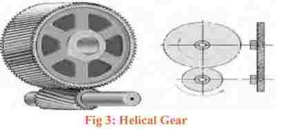
Helical Gears:
General: Helical gears are similar to the spur gear except that the teeth are at an angle to the shaft, rather than parallel to it as in a spur gear. The resulting teeth are longer than the teeth on a spur gear of equivalent pitch diameter. The longer teeth cause helical gears to have the following differences from spur gears of the same size
Limitations: Helical gears have the major disadvantage that they are expensive and much more difficult to find. Helical gears are also slightly less efficient than a spur gear of the same size.
Advantages: Helical gears can be used on non parallel and even perpendicular shafts, and can carry higher loads than can spur gears.
Bevel Gears:
General: Bevel gears are primarily used to transfer power between intersecting shafts. The teeth of these gears are formed on a conical surface. Standard bevel gears have teeth which are cut straight and are all parallel to the line pointing the apex of the cone on which the teeth are based. Spiral bevel gears are also available which have teeth that form arcs. Hypocycloid bevel gears are a special type of spiral gear that will allow nonintersecting, non-parallel shafts to mesh. Straight tool bevel gears are generally considered the best choice for systems with speeds lower than 1000 feet per minute: they commonly become noisy above this point. One of the most common applications of bevel gears is the bevel gear differential.
Limitations: Limited availability cannot be used for parallel shafts, can become noisy at high speeds.
Advantages: Excellent choice forintersecting shaft systems.

Worm Gears
General: Worm gears are special gears that resemble screws, and can be used to drive spur gears or helical gears. Worm gears, like helical gears, allow two non-intersecting 'skew' shafts to mesh. Normally, the two shafts are at right angles to each other.
A worm gear is equivalent to a V-type screw thread. Another way of looking at a worm gear is that it is a helical gear with a very high helix angle.Worm gears are normally used when a high gear ratio is desired, or again when the shafts are perpendicular to each other. One very important feature of worm gear meshes that is often of use is their irreversibility: when a worm gear is turned, the meshing spur gear will turn, but turning the spur gear will not turn the worm gear. The resulting mesh is 'self-locking', and is useful in ratcheting mechanisms.

Limitations: Low efficiency. The worm drives the drive gear primarily with slipping motion, thus there are high friction losses.
Advantages: Will tolerate large loads and high speed ratios. Meshes are self locking (which can be either an advantage or a disadvantage).
Racks (straight gears)
General: Racks are straight gears that are used to convert rotational motion to translational motion by means of a gear mesh. (They are in theory a gear with an infinite pitch diameter). In theory, the torque and angular velocity of the pinion gear are related to the Force and the velocity of the rack by the radius of the pinion gear, as is shown below: Perhaps the most well-known application of a rack is the rack and pinion steering system used on many cars in the past.
Limitations: Limited usefulness, difficult to find.
Advantages: The only gearing component that converts rotational motion to translational motion. Efficiently transmit power.Generally offers better precision than other conversion methods.
V.MAINTENANCE AND LUBRICATION:
Many bearings require periodic maintenance to prevent premature failure, although some such as fluid or magnetic bearings may require little maintenance. Most bearings in high cycle operations need periodic lubrication and cleaning, and may require adjustment to minimize the effects of wear. Bearing life is often much better when the bearing is kept clean and well-lubricated. However, many applications make good maintenance difficult. For example bearings in the conveyor of a rock crusher are exposed continually to hard abrasive particles. Cleaning is of little use because cleaning is expensive, yet the bearing is contaminated again as soon as the conveyor resumes operation. Thus, a good maintenance program might lubricate the bearings frequently but never clean them.
Packing:
Some bearings use thick grease for lubrication, which is pushed into the gaps between the bearing surfaces, also known as packing. The grease is held in place by a plastic, leather, or rubber gasket (also called a gland) that covers the inside and outside edges of the bearing race to keep the grease from escaping. Bearings may also be packed with other materials. Historically, the wheels on railroad cars used sleeve bearings packed with waste or loose scraps cotton or wool fiber soaked in oil, than later used solid pads of cotton.
VI. BRIEF DESCRIPTION ABOUT BEVEL GEARS
Bevel gears are used to transmit power between two non-parallel shafts. The shafts may be intersecting or non-intersecting. Bevel gears can be described as conical gears as they are cut on conical blanks (tapered). They are notinterchangeable and always designed in pairs. The commonly used bevel gears are: straight, spiral and hypoid based on the geometry.
Straight Bevel Gears:
The straight bevel gears are the simplest types of bevel gears. They are the important gears to transmit power between intersecting shafts. Straight bevel gears are shown in Figure below. The teeth are cut straight, have a taper, and if extended inward, would intersect each other on the axis of shaft. The meshing gears have line contact. Hence, they are not smooth in operation; generate more vibrations and noise at high-speed. They produce thrustload on shaft bearings. Straight bevel gears are used for speed ratio 1:1. Their precision is as good as parallel helical gears, but higher than crossed helical gears, spiral bevel gears, hypoid bevel gears and worm gears.

Spiral Bevel Gears:
These gears are mounted on shaft whose axes are intersecting. The pitch surface is conical as shown in Figure below. Spiral bevel gears have curved oblique teeth (spiral), which allow contact to develop gradually and smoothly.They have more contact length and area and less power transmission efficiency compared to straight bevel gears. They are useful for high-speed applications and others requiring less noise and vibration. They are difficult to design and costly to manufacture, as they require specialized and sophisticated machinery for their manufacture. They produce more thrust load on shaft bearings than straight bevel gears.

Their advantages compared with straight bevel gears at high speeds are: (a) smoothness and quietness of operation; (b) strength; and (c) durability due to the followings:
Longer contact length and larger contact ratio
compared to straight bevel gears of same size.
Teeth engage gradually, the contact beginning at one end and gradually working over other end; whereas in the straight bevel gear the contact takes place along the entire face of the tooth at the same instant.
Hypoid Bevel Gears:
Hypoid bevel gears are used to connect shafts whose axes do not intersect. They are very similar to spiral gears. However, their pitch surfaces are hyperpoloids rather than cones. As a result, their pitch axes do not intersect.They permit certain amount of sliding action along the direction of tooth element, which requires good lubrication. Their power transmission efficiency is poor compared to other straight and spiral bevel gears. In general, hypoid gears are most desirable for those applications requiring large speed reduction ratios, nonintersecting shafts, and also great smoothness and quietness of operation.

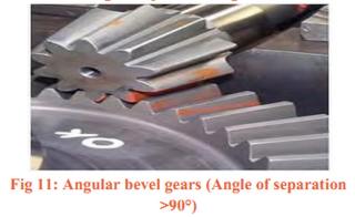
Miter and Angular Bevel Gears:
In majority of bevel gear drives, the shafts of the meshing gears are 90 grad to each other. If the angles between the shafts are 90°, and the two gears of a pairare having the same number of teeth, then it is called as “Miter Gear”. A pair of spiral miter gears is shownin Figure. In some bevel-gear drives, the angles between the shafts may not be 90°, but either more orless than 90°. These gears are called ‘Angular bevel gears’. A pair of angular bevel gears is shown in Figure below.

Applications of Bevel Gears:
Straight bevel gears are used primarily for low speed application with pitch line velocities up to 300 m/min. They are widely used in textile machines. Few of applications are listed below:
drive to bobbin rail on roving machine
drive between the doffer and feed roller on low speed carding machines
drive from calendar roller to coiler rollers, top coiler to bottom coiler plates in card, comber and drawing machine
drive between calendar roll and lap stop mechanism-lever in lap former of conventional blow room
VII. FABRICATION OF THE MACHINE
There are few types of fabrication methods that are
done on the machine. They are:
Arc cutting.
Drilling.
Grinding.
Turning.
Further Operation:
Cleaning.
Assembling.
Machining Operations:
In this paper it is used to cut the raw material such as plates, rod. This is done by arc cutting machine.
Drilling:
Drilling is used to produce holes in objects. In this project the square type pipe required the holes for making rake assembly. These holes are done by vertical type drilling machine.
Fine Grinding:
It is nothing but a grinding process, which is done as smooth with fine grains. It is done by convention grinding machine.
Turning:
It is used in this project to make the groove on the both sides of top cover plate. This is done by conventional lathe.
Further Operations:
Cleaning:
It is the operation to clean the all machined parts without burrs, dust and chip formals. By meaning the parts they are brightened and good looking.
Assembling:
It is the operation, its deals with the assembling of various parts produced by above operations.
VIII. CONCLUSION
The scotch yoke mechanism is made and its advantages and disadvantages are discussed. Its motion characteristics are studied. It is concluded that this mechanism is a good choice to convert rotating motion into reciprocating motion because of fewer moving parts and smoother operation. It can be used in direct injection engines like diesel engines, hot air engines. In this project report we provide an overview of the issues concerning different aspectsof multipurpose machine using scotch yoke mechanism. The paper focused on the principle of scotch yoke mechanism, type of tooling and machining parameters and process performance measure, which include cutting speed, depth of cut material removal rate with different type of equipments which can be run simultaneously and fabricate the work piece in multipurpose machine has been presented. The presented results can help to plan the machining of work piece with expected tolerance. The following major conclusions may be drawn from the study.
Multipurpose machine is derived from turning lathe which has been a well established industrial processes offering attractive capabilities for handling work piece of various length to be used at micro level. We have presentedthe development of multipurpose machine in various modes by which it can be actively adopted. We have explained the various parts and components of multipurpose machine using scotch yoke mechanism. Different types of attachmentsand tools which can be implemented on multi-purpose machine have been discussed.
REFERENCES:
1.Heinrich Arnold1 ”The recent history of the machine tool industry and the effects of technological change “University of Munich, Institute for Innovation Research and Technology Management, November 2001.
2. Dr. Toshimichi Moriwaki “Trends in Recent Machine Tool Technologies” Professor Department f Mechanical Engineering Kobe University ,NTN Technical Review No.74(2006).
3. T. Moriwaki “Multi-functional machine tool” ,Department of Industrial and Systems Engineering, Setsunan University, Neyagawa, Japan CIRP Annals - Manufacturing Technology DOI:10.1016/j.cirp.2008.09.004.
4. Frankfurt am Main “Multi-purpose machines ensure enhanced “, 1 January 11.
5. Selecting and Planning the Process of Manufacture: Dr. Pulak M.Pandey. http://paniit.iitd.ac.in/~pmpandey