Tomasz HANISZEWSKI
Silesian University of Technology, Faculty of Transport
Krasińskiego 8 Street, 40-019 Katowice, Poland
STRENGTH ANALYSIS OF OVERHEAD TRAVELING CRANE WITH USE OF FINITE ELEMENT METHOD
1. INTRODUCTION
The test object is one-girder overhead travelling crane with a hoisting capacity of 5 [t]. The beam is a typical welded box structure. Immutability of the geometric cross-section of the girder is being provided by located inside the welded membranes and stringers made from rolled channels. In addition to the girder, construction also includes two buffer beams and additional elements such as platform, hoisting winch of hoist drive.
The running rail of hoisting winch is attached to the girder. Inside the buffer beams the powered and non-powered wheel sets are located. As the crane is only a research and test object the maximum load (load capacity) is extremely rare.
2. GEOMETRICAL MODEL
In order to perform calculations using finite element method, a geometrical model of the crane structure was made according to the documentation of Research and Development Centre of Hoisting Machinery and Mechanical Conveying Equipment "Detrans" in Bytom. The model was entirely made иin Autodesk Inventor CAD system.
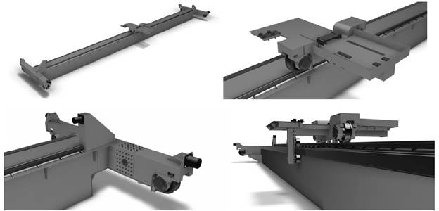
Figures 1, 2 shows buffer beams, hoisting winch and girder, Table 1 describes the masses and characteristic dimensions of the basic elements of crane. The tested crane is a thin-walled structure in which one dimension (thickness) is significantly smaller than the other. Such a structure is called a box girder, which has a high load capacity. In this case the ratio of the length to the thickness of individual sheets is much smaller than unity, which clearly confirms that the test structure should be treated as a surface. That is why discrete model will be built mostly from a shell elements.
3. FEM MODEL
In order to determine the stiffness and natural frequency a FEM model of the tested crane was made, which was used to carry out the calculations. For building a discrete model a shell first order elements S3, S4 with an average size of 30 [mm] and B31 beam elements were used. Shell elements were defined on the reference surface – midsurface of the steel sheets. Characteristics of the group of elements are defined by assigning to the section. As a result of the discretization a net consisting of 138155 elements was obtained. Sections of elements had the same thickness of the individual sheets and the material from which they were made. Load-carrying crane structure was built mainly from parts made of steel S235.
Rail was modeled using a B31 beam elements. Series of properties were assign to elements included in the so-called BEAM SECTION. To determine the cross-section of the beam and at the same time its properties, a two-dimensional grid of elements was set up in, for which the geometrical properties of the section are calculated numerically.
For such a model prepared in accordance with the scheme (Fig. 6) several loads were applied to the hoisting winch construction such as: gravitational force induced by the mass of the steel structure, wheel sets, welded rope drum with load, rope sheave with load, elements of traversing gear and hoist drive (gears, brakes, couplings, engines).
4. STRENGTH CALCULATIONS OF THE CRANE STRUCTURE
Calculations were performed using the computing cluster IBM BladeCenter HS21. Calculations were carried out in the Abaqus software shared for the calculation by the grant number: MNiSW/IBM_BC_HS21/PŚląska/021/2010 [10]. The most disadvantageous load case was assumed to simulate, when the hoisting winch is in the middle of the girder. Calculations were performed for load cases listed in Table 3
The simulation enabled to determine the location of stress concentration and displacement in the middle of the girder and also natural frequencies vibration forms. Determined value of the static deflection of unloaded structure (including gravitational force induced by the mass of the structure) was ust=11,2 [mm] for hoisting winch located in the middle of the girders span. In case of additional applied gravitational force induced by the mass of the load 5000 [kg] the static deflection value was ust=22 [mm].
In order to verify the results, the allowable girders deflection was checked according to the formula (1) [7]:
![]()
where: L – cranes span [m]; ust – girders static deflection in the middle of the span [m].
According to formula (1) [3] ratio of static deflection to the span of the bridge is 1,1·10-3 and is within acceptable limits. Stiffness of the cranes bridge was determined from the formula (2):

where: ku – stiffness of the structure [N/m]; ust – static deflection [m]; Q – gravitational force induced by the mass of the load and hoisting winch [N].
In this case, in accordance with (2) rigidity of the bridge cranes is considered as 4,65e6 [N/m]. Also reduced stress according to Huber-Mises-Hencky theory for the unloaded model (only gravitational force induced by the mass of the structure) and loaded one (gravitational force induced by the mass of the load 5000[kg] and of the hoisting winch) was determined.
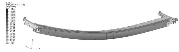
Reduced stress value for the unloaded construction in the middle of the cranes span was σ = 58[MPa], and for the construction loaded with gravitational force induced by the mass of the load 5000[kg] was σ = 164,4[MPa].
5. NATURAL FREQUENCY DETERMINATION
Each elastic system with linear characteristics has "n" degrees of freedom and "n" natural frequencies of oscillations. These are frequencies with which the system vibrates after the unbalance [4]. Each natural frequency corresponds to a certain form of vibration. Forced oscillations of any mechanical system are the result of the external variable force after natural vibrations damping. If the frequency coincides with one of the natural frequencies of the structure, there would occur a resonance phenomenon. The increase in the amplitude of vibration at resonance, leads to large displacements and strains, and thus to the dynamic loading of structural elements [6]. Calculation of natural vibration frequencies with a modal analysis, allows to avoid the phenomenon of resonance. In the case of the crane the significant impact on the structure will have all drives, which should be configured or designed to prevent formation of vibrations at a frequency close to the natural frequency of vibration of the structure, on which they are located.
Algorithms defining natural frequencies, usually calculate the desired number of low frequency vibration or frequency vibration of the selected band and their forms. Depending on the simplifications made in the discrete model building phase, frequency values will be appointed more or less accurate. During the calculations of test object Lanczos algorithm was used.
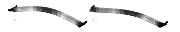
Lanczos algorithm is used to find the value of a large, symmetric matrix in a short time with a small estimate error of calculation. As a result of modal analysis for the values of natural frequencies and the corresponding modes of vibration were obtained. In Figures 10, 11 four forms of vibration are shown (crane load is worth 5000 [kg]), distinguishing the first form because it corresponds to the characteristic deflection when hoisting loads [9]. Table 5 lists the frequency of vibration under 5000 [kg] load and the set of frequencies for the load-carrying crane structure under no load.
6. CONCLUSIONS
Presented FE model can be the basis for further analysis, it is suggested to use the so called hybrid approach, combining the dynamic model with the FE model. This allows for identification of the state of stress and deformation during dynamic loads and at any chosen point of the structure. The work was co-financed by the European Union under the European Social Fund within the project "Activation of the academic community, as part of the Regional Innovation Strategy" POKL.08.02.01-24-019/08 ". Numerical calculations were carried out in the Abaqus system, shared under the grant number: MNiSW/IBM_BC_HS21/PŚląska/021/2010.
Bibliography
1. Gąska, D. & Pypno, C. Strength and elastic stability of cranes in aspect of new and old designи standards. Mechanika. 2011. Vol. 17(3). P. 226-231.
2. Haniszewski, T. & Gąska, D. & Matyja, T. Modeling assumptions influence on stress and strain иstate in 450 t cranes hoisting winch construction. Transport Problems. 2011. Volume 6. Issue 1. P. 11-19.
3. Jakubowicz, A. & Orłoś, Z. Wytrzymałość materiałów. Warszawa: WNT. 1984. [In Polish: Jakubowicz, A. & Orłoś, Z. Strength of materials. Warsaw: WNT.]
4. Kruszewski, J. & Sawiak, S. & Wittbrodt, W. Metoda sztywnych elementów skończonych w dynamice konstrukcji. Warszawa: WNT. 1999. [In Polish: Kruszewski, J. & Sawiak, S. & Wittbrodt, W. Rigid finite element method in the dynamics of the structure. Warsaw: WNT.]
5. Niezgodziński, M.E. & Niezgodziński, T. Zadania z wytrzymałości materiałów. Warszawa: WNT. 2005. [In Polish: Niezgodziński, M.E. & Niezgodziński, T. Tasks of the strength of materials. Warsaw: WNT.]
6. Parszewski, Z. Drgania i dynamika maszyn. Warszawa: WNT. 1982. [In Polish: Parszewski, Z. Vibrations and dynamics of machines. Warsaw: WNT.]
7. Piątkiewicz, A. & Sobolski, R. Dźwignice. Warszawa: WNT. 1969. [In Polish: Piątkiewicz, A. & Sobolski, R. Cranes. Warsaw: WNT.]
8. Reymer, B. (red.) Mały poradnik mechanika. Tom 1. Warszawa: WNT. 1994. [In Polish: Reymen, B. (ed.) Small tutorial of mechanic. Volume 1. Warsaw: WNT.]
9. Сладковский, А. & Ханишевский, Т. & Матыя, Т. Динамика мостового крана. Часть 1. Определение характеристик мостового крана. Вісник Східноукраїнського національного університету. 2010. No. 10 (152) ч.1. P. 200-205. [In Russian: Sładkowski, A. & Haniszewski, T. & Matyja, T. The dynamics of the bridge crane. Part 1. Determination of characteristics of the bridge crane. Journal of East-Ukrainian National University.]
10. Cyfronet AGH, 5. Available at: http://www.cyf-kr.edu.pl/uslugi_obliczeniowe/?a=mars.