
Abstract on the theme of master's work
Сontents
- Introduction
- 1. The relevance of the topic
- 2. The purpose and research tasks, planned results
- Review of research and development
- Substantiation of the structure and selection of rational parameters of the installation with non-sealed water collectors
- Сonclusions
- List of sources
Introduction
The main disadvantage of drainage systems of existing and projected coal mines is siltation of water catchments and intake wells. Cleaning of the solid material of these containers of existing structures is associated with a significant expenditure of manual labor. Their untimely cleaning results in the presence of solid particles in the evacuated water, sometimes inadmissible size, which leads to accelerated wear of the pumps.
The Donetsk National Technical University (DonNTU) has developed for district and main drainage systems, where the water from the shafts with a high concentration of solids comes in, the NUO-1 unit should be used, which eliminates the need for cleaning from solid water wells and intake wells. Flushing of sedimented sludge is carried out due to the fact that filling it occurs from the bottom up. Therefore, the sludge settles, basically, in the pit of the well of the tank.
the1. The relevance of the topic
he mining and geological conditions of the Donets Basin are among the most difficult in the world's coal industry. The main reasons for the complexities of mining and geological conditions in the Donbass are: a great depth of development, the presence of methane in the mines, and a high slope of bedding. More than 30% of coking coal, 15% - anthracite. The extraction is carried out in more than 150 mines. Almost 80% of the beds have a low power - up to 1 m. When mining coal seams, the mine water is an attendant factor. So, for 1 ton of coal mined by the mines of Donetsk, there are about 3 m3 of water.
Donbass is a region of old mines, where a relatively stable ratio of water inflows to various mining operations was established. Thus, for the Donbass mines, inflows up to 200 m3 / h prevail, including up to 50 m3 / h - 11%, 50 ... 100 m3 / h - 28%, 100 ... 200 m3 / h - 31%, 200 ... 500 m3 / h - 27% and 500 ... 1000 m3 / h - 3% [1].
2. The purpose and objectives of the study, the planned results
The purpose of research is to establish the basic laws governing the workflow and development techniques tunneling hydroelevating installation providing reducing the influence of water on the inflow prohodchikoa productivity and improving their working conditions, rational justification parameters and minimal installation dimensions. [2]
The main objectives of the study:
- Analysis of methods of pumping mine water.
- Evaluation of pumping methods.
- Compiling a mathematical model and searching for rational.
- Check the adequacy of the results.
Within the framework of the master's work, it is planned to receive actual scientific results in the following areas:
- Development of a schematic diagram for the installation with non-segregated water intakes.
- Compiling a mathematical model and using it to determine the rational parameters of an installation.
- The exception is the use of manual unskilled labor to clean the vessel of sludge.
- Pick up the minimum dimensions of the water collectors.
- Select the control system for the hydraulic elevator.
3. Review of research and development
The study of methods for cleaning the reservoir from large solid bodies in water was most actively carried out in the USSR, the Russian Federation and Ukraine, in particular at our university DonNTU. Therefore, it is quite a difficult task to review international sources, except for the USSR and the Russian Federation. Since, this installation was invented and designed in DonNTU.
The questions of use for the tunnel water drainage are considered in the works of V.M. Yakovleva, P.N. Kameneva, B.E. Friedman, N.N. Chernavkina, N.S. Bolotskikh, V.G. Geyer.
Schemes in which the hydroelevator pumped water into a small container, and then the water is pumped out by the pump, a bottom-hole vacuum water-lowering device was installed in the USV [3], proposed N. Bolotskykh.Schemes of application for downhole drainage during slope excavations are given by NN Chernavkin. and V.G. Geyer [4].
4. Substantiation of the structure and selection of rational parameters of the installation with non-sealed water collectors
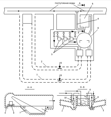
Figure 1 – Layout of underground drainage structures of the NUO-1 installation.
The drainage installation ( Fig.1 ) consists of a pumping chamber, an adjusting and emergency water collector, a preliminary settler and a receiving well.
List of components indicated on the schematic diagram:
- Adjustable water trap;
- Emergency catchment;
- Basic pumps;
- Groove;
- Preliminary settling tank;
- Water intake well;
- Slurry conveyor;
- Trolley;
- Hydraulic elevator of the adjusting header;
- Hydroelevator emergency catchment;
The NUO-1 scheme works as follows[8]. Mine water along the gutter groove 4 enters the preliminary settling tank 5. Where it is released from solid particles with a particle size of more than 0.1 mm. The solid particles settling in the preliminary settling tank are removed from it by means of a special slurry conveyor 7 onto a conveyor or into carts 8, which are directed to a skip or cellular lifting. From the pre-settling tank, partially clarified water enters the central receiving well 6. Filling it up to the level of the overflow canal, it begins to pour through it into the adjusting header 1. After filling it, the main pump 3 of the dewatering system starts and starts to pump water from the receiving well to the overlying horizon or surface.
In accordance with the safety rules, the NOU-1 scheme also includes an emergency catchment 2, the overflow channel of which is located higher than the adjusting header, and therefore the water begins to enter it only after the adjusting header is fully filled. The water from it is also pumped into the receiving well using a special pump or water heater 10.
The adjusting and emergency water collectors are made non-seizing and self-washed. This is provided by two factors:
- water fills the tanks from the bottom up with a low speed, so coal fines settle in the pit of the adjusting and emergency water collector, from where the hydroelevators are pumped into the central well and removed by the main pumps;
- flushing of the settled solid is carried out by water during the pumping of the tanks, for which the inclination angle of the sump soil is not less than 50, and the capacity is completely drained, since the soil of the sump is 0.5 m above the water level in the pit, ensuring free drainage.
Calculation of the main water-pumping unit with centrifugal pumps.
For the reliability of pumping water from the mine according to PB / 71, the delivery of each pumping unit must ensure the evacuation of the daily inflow of no more than 20 hours[12]. Therefore, the pump must be supplied at least:

Qol is the normal hourly inflow.
The required pump head is determined approximately by the dependence:
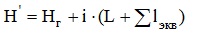
where Hg – is the geometric head.
L – is the length of the discharge pipeline.
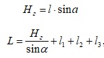
where a is the angle of inclination of the barrel, deg; l1 – length of pipes in the pump chamber from the receiving device of the most remote pump to the pipe walker; l2 – pipe length in the pipe run; l3 – length of pipes on the surface from the trunk to the discharge point;
For hydraulic impulse:
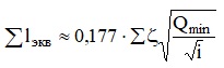
i – optimal hydraulic slope, which is taken in the range of 0.025 ... 0.05;
The sum l eqv – the equivalent length of all local resistances of the pipeline, is determined from the dependence: where 25 ... 30 – the sum of coefficients of local resistance of the pipeline.
Determining the size of the header
1) Adjusting capacity:
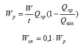
The minimum volume of the central catchment is determined from the conditions for ensuring the stability of the pump and hydraulic elevator operation and is applied equally.
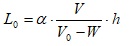
The cross-sectional area of ??the central well Ssk is selected from the conditions for placing suction pipelines and the convenience of their servicing. The depth of the central well hkk is determined by the formula:

The volume of the emergency capacity is calculated in accordance with the safety standards for the reception of a 4-hour normal inflow.
Taking the typical production cross-sections, and determining the volume of the emergency capacity:

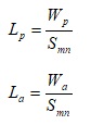
Find the length of the water collectors:
Acceptances in the well, where hydroelevators are installed, are carried out with a depth of 1.5 m, and the cross-section is assumed equal to the section of the wells. The diameters of the wells are determined constructively from the condition of providing in them the installation of pumping hydroelevators and observance of the necessary gaps for the movement of people along the installation ladder.
Calculation of pre-settling basin
The preliminary settling tank is in the form of a truncated pyramid. The width of the water mirror in it is 20 ... 30% less than the width in which it is built (Fig. 2). Taking the width of the settler B = 3 m, we determine the average speed of water movement in the settler.
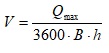
Pre-settling length:
The length obtained is not the minimum allowed. Proceeding from the structural features of the slag conveyor, we take the length of the settling tank to be 9.1 m.
The volume of the lower part of the preliminary settling basin is determined by the amount of solid precipitating out of the water during the day:
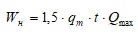
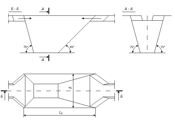
Figure 2 – Calculation scheme of the preliminary settler
Cleaning the pre-settler
As a method for cleaning the pre-settling basin from various methods, we take cleaning by means of a slurry conveyor (bagger-sumpf BZ-1), mounted in a preliminary settling tank. It provides loading of sludge and simultaneous dehydration.[7]
Bager-sumpf BZ-1 (Figure 3) consists of five sections: a section 2 comprising a drive head 1 and a reducer with an electric motor; two intermediate sections 3, 5 and two sections 4, 6 containing deflecting rollers 7, 8. The sections are covered by a conveyor scraper chain moving at a speed of not more than 0.1 m / s.
For the purposes of standardization and standardization, the drive head, the deflecting rollers and the scraper chain are used from the mass-produced conveyor SP63, and the reducer is from the winch type LRU1-2M. As the driving motor is adopted series of HLW in explosion-proof design.
Figure 3 – Removing particles larger than sm
(animation: 10 frames, 68.2 kilobytes)
(blue – water, gray – theslurry more than 0.1 cm.)
Conclusions
The master's thesis is devoted to the substantiation of the structure and the choice of rational parameters of the drainage installation. NUO-1 has a number of advantages: it excludes cleaning from a solid intake well and water collectors; in the process of exploitation it has a significant economic effect; the number of workers employed in servicing the water basin decreases; costs are reduced when it is used. The use of flushable water collectors allows maintaining the designed emergency capacity unchanged, improves the reliability of the drainage system, reduces the likelihood of pump failure due to fouling of receiving facilities, eliminates the laborious process of cleaning the water basins, allows pumps with a low positive geometric suction height and preserves the possibility of regulating energy consumption during peak hours of the power system .
When writing this essay, the master's work is not yet complete. Final completion: June 2018. The full text of the work and materials on the topic can be obtained from the author or his supervisor after the specified date.
List of sources
- Поджидаев В.Г. Горно геологические особенности разработки угольных месторождений восточного Донбасса – Научное сообщ. /УДК 553.9, М., 2000 – С. 367-369
- Яковлев В.М. Разработка гидроэлеваторной проходческой водоотливной установки – Д., 1987. – С. 5-16
- Болотских Н.С. Оборудовние водопонижения в угольной и горноугольной промышленности– М. Недра, 1973. – С. 101-164
- Гейер В.Г. Шахтные водоотливные установки. – М. Углетехиздат – 1948. – С. 277
- Братченко Б.Ф. Стационарные установки шахт – М. 2015. – С. 325-333
- Яковлев В.М. Вляние условий всасывания на максимальную подачу гидроэлеватора // Разработка полезных ископаемых – Киев, Техника – 1975. – С. 96-99
- Гейер В.Г., Тимошенко Г.М. шахтные винтеляторные и водоотливные установки –М., Недра, 1987 – С. 250-253
- Гейер В.Г., Антонов Я.К., Боруменский А.Г., Малеев В.Б., и др. Методические екомендациипо применению средств очистки шахтных водосборных емкостей – Д. ДПИ, 1983 – С.42-45
- Малеев В.Б., Данилов Е.И., Яковлев В.М., Специальные средства водоотлива и гидромеханизированной очистки шахтных водосборных емкостей – Д. ДПИ. 1986 – С. 16-24
- Акопов М.Г. Основы обогощения углей в гидроциклонах – М., Недра, 1967 – С. 178
- Гейер В.Г., Малеев В.Б., Данилов Е.И. Яковлев В.М. Методические рекомендации по применению средств механизации очистки шахтных водосборных есмкостей – Д., ДПИ, 1986 – С. 36
- Правила безопасности в угольных и сланцевых шахтах – М., Недра, 1986 – С. 67
- Указания по проектированию трубопроводов, прокладываемых в подземных выработках угольных и сланцевых шахт – МЦП-СССР. – М., 1974 г.
- Национальный открытый университет //ИНТУИТ [Электронный ресурс]: – Режим доступа: www.intuit.ru