
Abstract
The contents
- Introduction
- 1. Theme urgency
- 2. Goal and tasks of the research
- 3. An approach to the unification of synthesis of Moore FSM on FPGA
- Conclusion
- References
Introduction
Among the traditional methods of destruction of coals and rocks, the most widespread are drilling and blasting and mechanical (cutting and impact destruction). The search for new physical methods of destruction has not yet yielded serious positive results in the mining industry, so the improvement of traditional methods for today continues to remain an urgent task.
The drilling and blasting method, along with its main advantage – universality, has a number of serious shortcomings. Despite the recent modernization of its use of new explosives, improvement of drilling tools, blasting schemes, etc., increasing its manufacturability and safety, this method continues to cause concern for the consequences of its widespread use.
One of the most promising directions in this area is the use of high-speed water jets for cutting rock and hard materials. Hydro-jet technologies have been recognized around the world as one of the promising trends in the development of technology and technology, capable of addressing the issues of increasing productivity and safety of carrying out of clearing, preparatory and auxiliary works on mines. Absence of contact of the cutting tool (water jet) with the destroyed massif, the possibility of reducing metal consumption of downhole equipment with simultaneous increase of its power-to-weight ratio due to remote location of power equipment, effective protection of dust explosion protection are the main advantages of this method of destruction. On the other hand, the high energy intensity of hydraulic fracture is a factor restraining its widespread introduction to create executive bodies of rock-cutting machines.
1. Theme urgency
As the research results of a number of research institutes show, one of the promising directions in the field of rock destruction and other strong materials is the creation of the executive bodies of combines, which perform destruction by various combined methods. Most promising, in our opinion, is a method that combines the destruction of a percussion instrument and a high-pressure jet. It has several advantages, such as as an increase in the durability of the working tool, a decrease in the energy intensity of the process of destruction. Numerous developments of impact devices for destruction of the massif (hydraulic hammer), industrial oils are mainly used as a working fluid. For comparative analysis, Table 1 is given, in which shows the advantages and disadvantages of the basic methods of destruction. To create the combined organ of destruction, the most rational is a complex The use of a hydraulic breaker and a jet impeller operating on industrial water. This will make the process of destruction economical and environmentally friendly.
Table 1 – Basic methods of destruction
| Destruction method | Advantages | Disadvantages |
| Drilling and Explosion | The lowest specific energy consumption of destruction, the method is universal, has no limitations on the hardness of rocks | Complexity of organization of works, seismicity, high cost, increased danger, deterioration of ecological situation |
| Mechanical (cutting and impact destruction) | Cutting is limited to a strength of 40 MPa. Shock failure is used for any breeds | Increased mass, noise, vibration, leakage of working fluid, fluid emissions into the atmosphere |
| Hydraulic (stationary medium pressure jet) | Intrinsically safe method of destruction | It is necessary to extinguish the reflected jet, it is necessary to remove liquid |
| Hydraulic (high-pressure pulse jet) | Absence of a reflected jet, there is no need to remove the liquid | The presence of vibration and noise, the complexity of the design of the pulse generator |
| Others (electrophysical, chemical) | Prospects of nonmechanical destruction | Limited area of application |
The master's work is devoted to the actual scientific task – the development and substantiation of the structure and the choice of rational parameters of the mechanism for combined fracture method, using a hydraulic hammer and a jet impulse as a working member.
2. Goal and tasks of the research
The aim of the study is to develop and substantiate the structure, the choice rational parameters of the mechanism for impact-jet destruction.
Main research tasks:
- Analysis of methods of destruction of hard rocks.
- Evaluation of methods of destruction.
- Creation and evaluation of mechatronic block for impact-jet destruction.
- The compilation of a mathematical model and the search for rational parameters of the mechanism.
Object of study: destruction of solid materials in a combined way.
Subject of study: mechatronic block of combined destruction, combining hydraulic hammer and hydraulic impulse.
Within the framework of the master's work, it is planned to receive topical scientific results in the following areas:
- Development of a schematic diagram for a mechatronic block of impact-jet destruction.
- Compiling a mathematical model and using it to determine the rational parameters of a mechatronic block.
- Creation of the mechatronic control system of the mechanism.
3. Structure Substantiation And Rational Parameters Searching Of The Mechanism For Impact-Jet Destruction
Mechatronics – studies the synergetic combination of precision mechanics with electronic, electrotechnical and computer components for the purpose of designing and producing qualitatively new modules, machines, systems and machine complexes with intellectual control and their functional movements. In modern mechatronic systems for the realization of high quality and accuracy of motion are applied methods of intelligent control. This group of methods is based on new ideas theory of control of modern hardware and software means of computer technology, perspective approaches to synthesis controlled motion of mechatronic systems. To use the methods of computer-aided design form interconnected functional, structural and constructive models of mechatronic modules, then plan the movement of mechatronic systems in space and time, optimizing them, for example, by the criterion of maximum speed.
The main advantages of these mechatronic systems are the exclusion of a multistep transformation of energy and information, simplification of kinematic circuits and, consequently, high accuracy and improved dynamic characteristics, design compactness of modules, improved weight and size characteristics. The possibility of combining mechatronic modules into complex mechatronic systems, and complexes that allow for rapid reconfiguration, relatively low cost of installation, configuration and maintenance of the system, due to the modularity of the design, unification hardware and software, the ability to perform complex movements, through the use of adaptive and intellectual management. These advantages of the mechatronic control system can be used to create a customizable mechatronic block of the mechanism of impact-jet destruction.
The search for new physical methods of destruction has not yet yielded serious positive results in the branches of the national economy, so the improvement traditional ways to date continues to be an urgent task.
One of the most promising directions in this area is the use of high-speed water jets for cutting rock and hard materials. Hydrojet technologies have been recognized all over the world as one of the promising trends in the development of technology and technology capable of to solve questions of increase of productivity and safety of carrying out of clearing, preparatory and auxiliary works. Absence of contact between the cutting tool (water jet) and the material to be destroyed, the possibility of reducing the metal capacity of equipment while simultaneously increasing its power-to-weight ratio due to the remote location of power equipment, effective protection of dust explosion protection are the main advantages of this method of destruction. On the other hand, The high energy intensity of hydraulic fracture is a factor restraining its widespread introduction to create executive bodies of rock-cutting machines.
A schematic diagram of the proposed shock-jet device is shown in Figure 1.
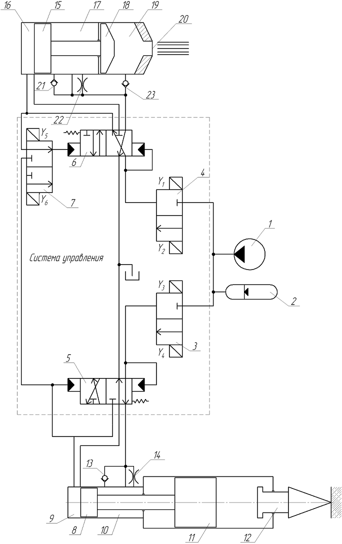
Figure 1 – A schematic diagram of the proposed shock-jet device
Designations: 1 – pumping station; 2 – hydropneumatic accumulator; 3, 4 – two-position distributor with electrical control; 5, 6 – three-line two-position distributor with hydraulic control; 7 – two-position double-line distributor; 8 – hydraulic breaker piston; 9 – the piston chamber of the hydraulic breaker; 10 – rod chamber of the hydraulic breaker; 11 – the firing pin; 12 – the executive body; 13 – check valve; 14 – throttle; 15 – the impulse piston; 16 – the piston chamber of the impulse; 17 – rod chamber of the impulse; 18 – displacer; 19 – displacement chamber; 20 – nozzle; 21 – check valve; 22 – throttle; 23 – non-return valve.
In this scheme, the working cylinder is designed as a double acting cylinder. its working chambers are alternately connected to the pressure and drain lines, and reversing movement of the piston is carried out by means of a two-position spool valve with position feedbacks of the piston.
1) Only the hydraulic hammer – in the initial position, the valve spool 5 under the action of the spring installed under its end is in the position providing the connection of the piston cavity of the working cylinder 10 (the chamber of idling) with the pressure line, and the piston cavity 9 with the line plum. When the pump 1 is turned on, the piston 8 moves faster to the left, displacing fluid from the piston cavity in drain line. After moving to a predetermined distance, the piston overlaps the drain holes in the cylinder liner, the pressure above the piston rises, acts on the end of the spool 5 and switches the latter to the position of the working stroke, those. connects the piston cavity 9 with the pressure chamber, and the stem cavity 10 with the drain line. The piston 8 is decelerated and begins to accelerate towards the tool 12. Immediately before impact, the piston 9 opens the bore, which connects through the check valve 13 a piston cavity with a drain line. As a result, the pressure in the piston cavity 9 and above the end of the spool 5 falls to a value at which the spring switches the spool into position a platoon of a striker. A striker 11 strikes the tool 12, then the hammer cycles repeat. To prevent impact of the piston 8 and 15 against the wall of the cylinder during the impact, the throttle 14 and 22 are installed.
2) Only the hydraulic impulse – the work of the impulse is completely identical to the operation of the hydraulic breaker. The shot fluid arrives, at the time of plunging the piston 15, into the chamber 19 through the check valve 23. The distributor 7 serves to select the source for the feedback. In this mode, the fluid for feedback comes from chamber 16.
3) Combined mode – the hydraulic hammer and hydraulic impulse generator alternately operate. This mode is realized by switching the distributor 7 and connecting the spool end 6 to the cavity 9.
The principle of the combined shock-jet mechanism is presented in the animated image (Fig. 2).
Figure 2 – The principle of the combined shock-jet mechanism
(animation: 8 frames, 83.7 kilobytes)
(blue – connection to the pressure line, red – connection with a drain line)
Select the operating mode mechatronic unit by pressing the button corresponding to the desired mode. An example of this panel is shown in Figure 3.
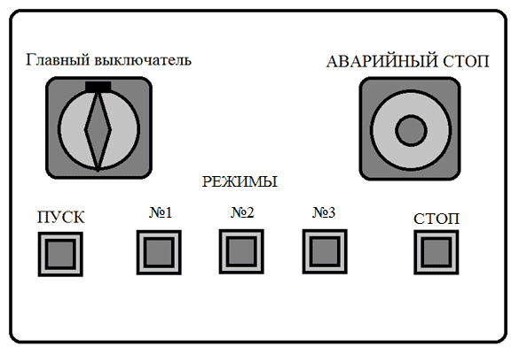
Figure 3 – Control Panel
To compile a mathematical model, we compile a calculation scheme (Fig. 4) and assume that there is no inertia in the control system block, and the piston and The rod cavities in the working bodies are alternately connected to the discharge and discharge lines. The model is chosen with concentrated parameters and the differential equations of motion of the hammer and impulse pistons are compiled.
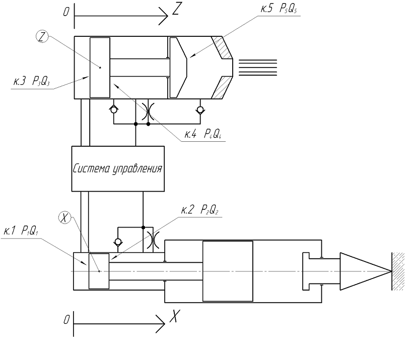
Figure 4 – Calculation scheme
Movement of the piston-hammer of the hydraulic hammer (X) and the impulse (Z):
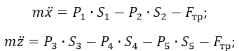
where P1, P2, P3, P4, P5 – liquid pressure in the corresponding chamber;
S1, S2, S3, S4, S5 – the area of the piston in the corresponding chamber;
Fтр – frictional force in seals:
For the hydraulic hammer:
For the hydraulic impulse mechanism:
where f – coefficient of friction in the seal;
D – diameter of piston, corresponding device;
d – stem diameter of the corresponding device.
The system can be in two states - a blow (shot) or cocking. This means that two equations are required to determine the parameters:
1) Impact of the hydraulic hammer:
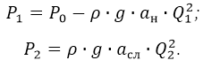
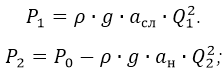
where Р0 – pressure generated by the pumping station;
ан и асл – resistance in discharge and discharge lines;
Q1 и Q2 – costs in the piston and rod chamber respectively.
2) Cocking of the hammer:
For the hydraulic impulse mechanism:
Shot of the hydraulic impulse mechanism:
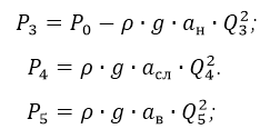
2) Cocking of the hydraulic impulse mechanism:
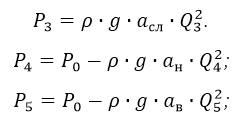
где Q3, Q4 и Q5 – costs in the piston, rod and displacement chamber, respectively; ав – line resistance.
The flow rate is determined:
where S – the surface area of the piston in the required chamber.
These equations of motion can be used to model the process of operation of the system and to find power indicators of the breaker and impulse – the impact energy of the hydraulic breaker, the frequency of operation, the energy of the pulse hydraulic impulse and flow in the displacement chamber.
Conclusion
The master's thesis is devoted to the substantiation of the structure and the choice of rational parameters of the mechanism for impact-jet destruction. At this stage, the scheme of the device for impact-jet destruction is described. It is taken as the base for further work. This circuit diagram will be used to build a 3D model combined working organ. A block diagram was constructed to describe a mathematical model with an instantaneous switching in the control system. This model will be used to find the energy parameters of the system for the subsequent rationalization and optimization of the parameters of the working body and the required hydraulic equipment.
When writing this paper the master's thesis isn't completed yet. Final end: June, 2018. The full text of work and materials on a subject can be received from the author or his scientific supervisor after the specified date.
References
- Кузьмин И.А., Рутберг М.И., Мерзляков В.Г. Выбор эффективной схемы комбинированного разрушения горного массива высоконапорной струей воды и дисковой шарошкой. – Научное сообщ. /ИГД им. А.А. Скочинского, 1984, вып. 230, с.86 – 90
- Лабутин В. И. Перспективы применения комбинированного способа разрушения горных пород – /Горный информационноаналитический бюллетень. – 2015. – №12. – С. 325-333
- Мерзляков В. Г. Опыт применения гидравлических струй высокого давления при создании эффективных средств разрушения горных пород /Маркшейдерский вестник. – М., 2010. – №1 (январь-февраль) – С. 33-39.
- Лабутин В.Н. Комбинированный способ разрушения при выемке угольных пластов с породными включениями – /Горный информационноаналитический бюллетень. – 2015. – №12. – С. 325-333
- Лабутин В.Н.,Марков В.С. Перспективы применения комбинированного способа разрушения горных пород – /Горный информационноаналитический бюллетень. – 2015. – №12. – С. 325-333
- Савченко Н. В., Яхно О. М. Гидродинамические способы создания пульсирующих струй для гидроразрушения твердых материалов -/НТУУ «КПИ». – 2002. – №4. – С. 67
- А. с. 4450319 А1 СССР : E21C 37/00. Ударно-струйное гидравлическое устройство / правообладатели: В.Д. Павленко, Ю.Н. Голубейко, В.Г. Татарко, Л.Ф. Федоров – № 1555474; заяв. 28.06.1988; опуб. 07.04.1990 Бюллетень №3. – 2 с.
- Бойко Н. Г., Коломиец В. С., Геммерлинг О. А. Определение рациональной частоты струи гидроимпульсной установки для проведения добычных работ /Наукові праці Донецького національного технічного університету. Випуск 18(172), серія гірничо-електромеханічна. - Донецьк: ДВНЗ «ДонНТУ», 2010. - С.124-130
- Устименко Т.А., Кононенко А.П., Селивра С.А., Яценко, А.Ф., Математическая модель рабочего процесса гидравлического ударного механизма /Наукові праці Донецького національного технічного університету. Випуск 16(142), серія гірничо-електромеханічна. – Донецьк: ДВНЗ «ДонНТУ», 2008.– 306 с.
- А.с. 3868919 А1 СССР : E21C 37/00. Ударно-струйное гидравлическое устройство / правообладатели: Г.М. Тимошенко, С.А. Селивра, П.Ф. Зима, В.Г. Тимошенко, А.Ф. Яценко, В.И. Сикорский – №1286762; заяв. 14.03.1985 ; опуб. 30.01.1987, Бюллетень №4. – 3 с.
- Худин Ю.Л., Маркман Л.Д., Вареха Ж.П., Цай П.М. Разрушение пород комбинированными исполнительными органами – М., Недра, Ц 1978 – 60с.
- Коняшин Ю. Г. Эффективность применения статического и ударного способов разрушения горных пород различной крепости // Научные сообщения. – М.: ИГД им. А.А. Скочинского, 1974. – №125.
- Сигаев Е.А. Исследование гидроотбойки пульсирующими гидроманиторными струями //Известия ВУЗов. Горный журнал, 1964. – Вып. 2.