
Abstract on the theme of master's work
Content
- Introduction
- 1. Relevance of the topic
- 2. Purpose of development
- 3. Analysis of modern developments in the field of robotics in surgery
- 3.1 Analysis of the main types of actuating actuators for displacement and manipulation
- 3.2 Analysis of methods and means for measuring high-precision linear displacements
- 3.3 Statement of the problem of designing a device for high-precision movements in surgery
- 4. Development of the design of the projected device
- Сonclusions
- List of sources
Introduction
At present, under the conditions of relative stabilization of the growth in demand for industrial robots of medium payload, there has been a clear trend towards an increase in demand for light and ultra-light robots. This is mainly due to the fact that ensuring the accuracy and stability of many processes and operations, including assembly, in conditions of expanding nomenclature and small-series production is impossible without the use of industrial robots. Automation based on industrial robots is undoubtedly the highest step in the creativity of many generations of people in their quest to create themselves universal assistants. Robots in medicine have been around for more than 25 years. When the development of space programs began in the United States, the question arose of what to do if astronauts, during their stay in orbit, needed urgent surgical help? Of course, for this it was not practical to create a separate a space station or a module in which a traditional operating theater would be located and a team of surgeons was permanently stationed. To solve this problem, NASA specialists developed a surgical robot that was controlled by physicians and engineers from the Earth on the basis of an analysis of the individual state of the astronaut. The technologies, developed earlier in the space and military spheres, have led to the emergence of robots in medicine that allow the most accurate to perform the most complicated surgical manipulations. And although the android-doctor, completely replacing man, described in the fantastic literature has not yet been invented, there are robots that perform certain functions much better than the most experienced live surgeons.
1. Relevance of the topic
On the creation of high-precision mechanisms and systems of robots for miniature products of technical literature at present, virtually no. Many methods of ensuring high accuracy of robots still remain to some extent a lot of art in technology and mechanics. All this confirms the relevance and complexity of the task set in the work.
2. Purpose of development
The purpose of the development is to increase the accuracy of linear displacements manipulator robot-surgeon with the appropriate formation of control signals by its actuators.
3. Analysis of modern developments in the field of robotics in surgery
One of the best developments in this field is the universal robot surgeon Da Vinci from Intuitive Surgical Inc. This is a universal robotic system used by clinics around the world. With the help of Da Vinci perform operations on a variety of organs. A photo of the work of the universal robot surgeon Da Vinci is shown in the figure. 1.1
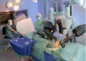
Рисунок 1 – Photo of work of universal robot surgeon Da Vinci from the company Intuitive Surgical Inc
The robot consists of two blocks. One is for the operator, and the second - a four-armed machine plays the role of a surgeon. The doctor sits down behind a convenient console that allows you to see the operated area in 3D with multiple magnifications and uses special joysticks to control tools. A significant increase in the image, the ability to display three-dimensional and conventional two-dimensional images on the monitor, allow the surgeon to obtain the most accurate picture of the operable site. Da Vinci is equipped with special mechanical devices, repeating the functions of human hands, while they have in diameter only one centimeter. Thus, the risk of getting into the wound is significantly reduced infection, and a contact equipment with notch fabrics. Now in America, approximately 80% of prostatectomy for prostate cancer is performed with the help of Da Vinci. The spread of technology is associated with significant advantages of the robotic system: postoperative pain decreases, bleeding decreases and scars are minimized. Eventually, the patient quickly restores and returns to normal. Technology is improving over time: the other day the famous robot-surgeon held the first independent in the history of medicine-without the participation of a human-operation: he removed the gallbladder with a bad outflow. The robot was insured by an experienced surgeon who was ready to continue working at any time, but his intervention during the operation was not necessary. There are other talented robotic surgeons in the world. A group of researchers from the Canadian city of Kalagari, led by a neurosurgeon Garnett Sutherland, combined a surgical robot with a tomograph. Robotic surgeon NeuroArm is operated by a surgeon with the help of special manipulators that accurately convey the movements of his hands to automated tools. Photo of the appearance of the robot-surgeon NeuroArm is shown in Fig. 1.2 [1]. During the work the doctor can in real time observe the magnetic resonance imaging of the brain in the 3D image, and also monitor his work on the video output to the surgical microscope. According to Garnett Sutherland, the robot sees much more, and this provides greater accuracy of the surgeon's movements. So, a level of accuracy of about 1 millimeter is available to a person, while a robot can reach 30 microns. This accuracy allows for operations at the cellular level.
3.1 Analysis of the main types of actuators movement and manipulation
Functional in the structure of robots for miniature products can be identified the following components: executive and control device, working body and information system. The executive device ensures the performance of all motor functions of the robot, is a set of movably connected links and constructively consists of the following main nodes: carriers structures, drives, transmission and actuating mechanisms. The information system provides reception of information about the state of the industrial robot and the external environment, the transformation and transfer of information to the control device, as well as the exchange of information between the robot and another device and operator working with it. The control unit (control system) provides the possibility of programming the robot, storing the program, as well as reproducing it, correcting and debugging it. It is designed to generate and issue control actions to the executive system in accordance with the specified control program; organizes the work of the information system and synchronizes all the processes of information exchange between the robot and various external devices. Creation of an industrial robot for small and miniature products is associated with the development and improvement of each of these systems, and the specifics of such robots are determined by the need to provide comparatively high requirements for positioning accuracy and reliability.
3.2 Analysis of methods and means for measuring high-precision linear displacements
Tensometric methods for measuring linear displacements Strain gages among all strain gauges have found the widest application. Changes in the shape of any part due to the action of external or internal forces, which are accompanied by distortion (deformation) of its surface. The strain gage fixed on this surface perceives deformation of the measurement object and at the same time changes its electrical resistance. The change in resistance is a measure of the deformation that has arisen, it can be measured by devices connected to strain gages, which show or register. The strain gauge is a passive transducer, therefore it is necessary to give it power from an electrical voltage source, and for this you can use both a constant and an alternating voltage. The design of the strain gage is shown in Fig. 1.11. The sensitive element of strain gauges is the so-called grating made of a thin electrical conductor. In the usual forms of performance a thin-film polymer substrate is electrically insulated from the object of measurement. It is transferred to deformation and protects from damage. To facilitate the connection of the wires, solder points, strip or thin wire terminals are used.
Methods for measuring the movement from the electrical conversion system With the help of strain gauges, the change in the length of a certain base is measured. This change is determined by the movement of the movable reference prism relative to the fixed point. A signal taken from such a strain gauge, proportional; Thus, they are very close to the displacement transducers and differ from the latter not in accordance with the principle of measurement, but only in shape and detail of the design in accordance with the measurement tasks. Systems of this type are usually called strain gauges, since they, as a rule, allow us to determine the relative strain.
3.3 Statement of the problem of designing a device for high-precision movements in surgeons
Разрабатываемое устройство предназначено для измерительного контроля перемещений робота-хирурга. Устройство должно быть разрабо-тано на основе микропроцессорной системы, передавать полученную ин-формацию с датчиков линейного перемещения для дальнейшей обработки с формированием соответствующих воздействий для манипуляции робота-хирурга. Для формирования сигналов управления исполнительными механиз-мами робота-хирурга необходимо выполнять контроль линейного переме-щения для двух диапазонов измерения, при этом второй диапазон измерения составляет от 0 до 10 мм и предназначен для начального определения пере-мещения. Первый диапазон, который осуществляет измерения в диапазоне от 0 до 2 мм, предназначено для окончательного определения перемещений. Относительное значение линейного перемещения измеряется первич-ными преобразователями линейного перемещения. Рассчитывается относи-тельное и абсолютное значение линейного перемещения и передается в устройство, которое выполняет расчет значения перемещения. Если относительное значение выходит за пределы допусков, устройство передает информацион-ные сигналы на исполнительные механизмы робота-хирурга для корректи-ровки процесса перемещения. Разрабатываемое устройство должна входить в состав более сложной автоматизированной системы контроля и управления перемещением и мани-пуляциею робота-хирурга. Конструктивно устройство должно быть пред-ставлено в виде двух блоков: схемы согласования с измерительными датчи-ками и цифрового блока, выполняющего все необходимые расчеты и связь с центральным процессором робота-хирурга. Устройство измерительного контроля линейного перемещения робота-хирурга должно удовлетворять следующим требованиям: – первый диапазон измерения перемещения, мм от 0 до 2; – значение абсолютной погрешности измерения первого диапазона перемещения, мм не более 0,01; – второй диапазон измерения перемещения, мм от 0 до 10; – значение абсолютной погрешности измерения второго диапазона перемещения, мм не более 0,05; – диапазон изменения выходного тока кабельного усилителя, мА от 0 до 5; – диапазон изменения входного напряжения АЦП, UIN, B от 0 до + 5. Для обеспечения этого необходимо выбрать тип первичного преобра-зователя перемещения, разработать схему передачи информации в микро-процессорный блок, разработать структурную схему устройства, а также разработать конструкцию внешнего вида корпуса.
4. Development of the design of the projected device
When designing robot designs, much attention is paid to the choice of the coordinate system in which hand movement should be carried out. In the robot manipulator designs, rectangular, cylindrical and spherical coordinate systems can be used. Manipulators operating in a rectangular coordinate system are often most often devices installed in a carriage that is suspended on rails below or above the equipment being serviced. The hand of such a manipulator can be lowered, moved relatively carriage in the transverse direction and along with the carriage - along the guides. In Fig. 4.1 shows the scheme of the manipulator with four degrees of freedom, in which the hand 3 with the brush 2 has three degrees of freedom, moving in a moving system of rectangular coordinates associated with the turntable 4. The fourth degree of freedom is realized when the table is rotated about the vertical axis. The fifth independent movement is the movement of grasp. In the implementation of any movement when the turntable 4 is stopped, the part held by the gripper 1 does not change its orientation in space. Orientation in the horizontal plane changes when the table is rotated. The design ensures the straight movement of the part when it is installed in the equipment. This quality becomes especially valuable when performing a number of operations. In this case, when moving an object on some other trajectory (for example, along an arc of a circle), an increased accuracy of the movement is required, or the use of special grips that provide some freedom to hold the part in one or two coordinates. When the robot arm moves in a cylindrical coordinate system, the orientation of the part in the horizontal plane also changes, so that if it is necessary to restore the original position of the part, it is corrected by turning the brush around the vertical axis. The ability of the manipulator's arm to move in a cylindrical coordinate system can be used when servicing a large number of processes. The presence of two rectilinear movements facilitates the development of layouts of workplaces of equipment with a robot, an assessment of that; and other specific applications, the calculation of the working cycle time, etc. In the constructions of these manipulators for orientation in space, usually no more than two degrees of freedom are provided.

Figure 4.1 - The scheme of the manipulator with four degrees of freedom
In some cases, manipulators with a large number of degrees of freedom are created. It is established that it is often more profitable to have one or more additional degrees of freedom in the construction than to create a large number of special feeding and orienting devices, and also to re-move and reinstall the equipment. Additional degrees of freedom should also be envisaged when the manipulator's hand has to be obstructed and when straight-line movement is required to insert a part into the work area. Therefore, to give greater flexibility, flexibility, and the ability to work in hard-to-reach places, robot manipulators with six, seven, eight or more degrees of freedom are created. An additional degree of freedom appears when the robot is mounted on the wheels, the base model of which is fixed on the floor. In this case, the robot can move along the guides, reinforced on the floor or on the crane-beam.
Сonclusions
The executive device for high-precision movements in surgery, which is designed for measuring control of linear Movements of the manipulator of the robot-surgeon. This device is included in the the composition of the automatic control and manipulation system of the manipulator of the robot-surgeon's movement.
The purpose of the development is to increase the accuracy of linear displacements manipulator robot-surgeon with the appropriate formation of control signals by its actuators.
The device is intended for measuring control of linear Moves the manipulator of the surgeon's robot in two measuring ranges: from 0 to 10 mm and from 0 to 2 mm.
Structurally the device is represented in the form of two blocks: circuits coordination with measuring sensors and a digital performs all necessary calculations and communication with the central processor robot-surgeon. The device provides: - the first measuring range of the movement, mm from 0 to 2; - value of absolute measurement error the first range of movement, mm, not more than 0.01; - the second measuring range of displacement, mm from 0 to 10; - value of absolute measurement error second travel range, mm, not more than 0,05; - range of output current variation cable amplifier, mA from 0 to 5; - range of input voltage variation of ADC, UIN, B from 0 to 5; - the shape of the output voltage GHS is sinusoidal; - effective value of voltage ГГС, В 2,5; - stability of the amplitude,% not more than 0.1; - frequency of oscillations of GGS, kHz from 3 to 5; - relative frequency instability The output of the GGS is not more than 10-3; - output current GGS, mA not less than 100; - output power, W not less than 0.25.
List of sources
- Да Винчи со скальпелем: топ-5 роботов-хирургов и медсестра в придачу [Электронный ресурс]. – Режим доступа: http://www.dsnews.ua/future/da-vinchi-so-skalpelem-top-5-robotov-hirurgov-i-medsestra-16092014131500. – Дата доступа: июнь 2016. – Загл. с экрану.
- Бансявичюс Р.Ю. Промышленные роботы для миниатюрных изделий / Р.Ю. Бансявичюс, А.А. Иванов, Н.И. Камышный и др.; под ред. В.Ф. Шаньгина. – М.: Машиностроение, 1985. – 264 с.
- Андреенко С.Н. Проектирование приводов манипуляторов / С.Н. Андреенко, М.С. Ворошилов, Б.А. Петров. – М.: Машиностроение.Ленингр. отд-ние, 1975. – 312 с.
- Егоров Ю.Н. Системы привода роботов / Ю.Н. Егоров. – Л.: Изд. ЛГУ, 1982. – 336 с.
- Иванов А.А. Проектирование систем автоматического манипулирования миниатюрными изделиями / А.А. Иванов. – М.: Машиностроение, 1981. – 272 с.
- Кулешов В.С. Динамика систем управления манипуляторами / В.С. Кулешов, Н.А. Лакота. – М.: Энергия, 1971. – 304 с.
- Медведев В.С. Системы управления манипуляционных роботов / В.С. Медведев, А.Г. Лесков, А.С. Ющенко. – М.: Наука, 1978. – 416 с.
- Промышленная робототехника /под ред. Я.А. Шифрина. – М.: Машиностро-ение, 1982. – 415 с.
- Попов Е.П. Манипуляционные роботы. Динамика и алгоритмы / Е.П. Попов, А.Ф. Верещагин, С.Л. Зенкевич. – М.: Наука, 1978. – 398 с.
- Бансявичюс Р.Ю. Вибродвигатели / Р.Ю. Бансявичюс, К.М. Рагульскис. – Вильнюс: Мокс- лас, 1981. – 192 с.
- Клингман Э. Проектирование микропроцессорных систем / Э. Клингман; пер. с англ.; под ред. С.Д. Пашкеева. – М.: Мир, 1980. – 572 с
- Андрианов Ю.Д. Управляющие системы промышленных роботов / Ю.Д. Андрианов, Л.Я. Глейзер, М.Б. Игнатьев и др. – М.: Машиностроение. 1984. – 288 с.
- Вульфет Дж. Датчики в цифровых системах / Дж. Вульфет; пер. с англ. под ред. В.В. Малова. – М.: Энергоатомиздат, 1981. – 200 с.
- Аш. Ж Датчики измерительных систем / Ж. Аш. – М.: Мир, 1992.–480с.
- Схемотехніка електронних систем: підруч. для вищ. навч. закл.: у 3 т. Т. 1 Аналогова схемотехніка та імпульсні пристрої; Т. 2 Цифрова схемотехніка; Т. 3 Мікропроцесори та мікроконтролера / В.І. Бойко, А.М. Гуржій, В.Я. Жуйков, А.А. Зорі, В.М. Співак, Т.О. Терещенко. – 2-ге вид., допов. і переробл. – К.: Вища школа, 2004. – 1188 с.
- Основи технічної електроніки: підручник у 2 т. Т. 2. Схемотехніка / В.І. Бойко, В.Я. Жуйков, А.А. Зорі, В.М. Співак, Т.О. Терещенко. – К.: Вища шк., 2007. – 512 с.
- Скаржепа В.А. Электроника и микросхемотехника: сборник задач /В.А. Скаржепа, В.И. Сенько; под. общ. ред. А.А. Краснопрошиной. – К.: Вища школа, 1989. – 232 с.
- Терещук Р.М. Полупроводниковые приемно-усилительные устройства: спра-вочник радиолюбителя / Р.М. Терещук, К.М. Терещук, С.А. Седов. – 4-е изд. стер. – К.: Наукова думка, 1989. – 800 с.
- . Гусев В.Г. Электроника и микропроцессорная техника: учеб. для вузов / В.Г. Гусев, Ю.М. Гусев. – 4-е изд., доп. – М.: Высш. шк., 2006. – 799 с
- Хоровиц П. Искусство схемотехники: монография / П. Хоровиц, У. Хилл; пер. с англ. – 7–е изд., перераб. и доп. – М.: БИНОМ, 2009. – 704 с.
- Щербаков В.И. Электронные схемы на операционных усилителях: [справоч-ник] /В.И. Щербаков, Г.И. Гнездов. – К.: Техника, 1983. – 213 с.
- Титце У. Полупроводниковая схемотехника: в 2 т.: пер. с нем. – Т.1. –/У. Титце, К. Шенк. – М.: Додэка–ХХI, 2008. – 832 с.
- Опадчий Ю.Ф. / Аналоговая и цифровая схемотехника (Полный курс): учеб-ник для вузов / Ю.Ф. Опадчий, О.П. Глудкин, А.И. Гуров; под ред. О.П. Глудкина. – М.: Горячая Линия – Телеком, 2000. – 768 с.