
Abstract
Contents
- Introduction
- 1. Theme urgency
- 2. Goal and tasks of the research
- 3. Research overview
- 4. Propagation of radio waves
- 4.1 Features of propagation of radio waves in the room
- 4.2 Influence of building materials, equipment and furniture on signal propagation
- 5. Ray tracing
- 6. Building of room model
- 7. Building of field distribution
- Conclusion
- References
Introduction
Recently, the formation of the community, to a greater extent meets with the problems of ensuring the safety and protection of human beings. In Ukraine, such difficulties, relating to man and the environment, are growing every day. Such difficulties are solved with the use of modern technologies and telecommunications equipment. In this regard, the growth rate of wireless networks in buildings is growing. To date, wireless technologies are actively being introduced and are not inferior to the development of other communication technologies. These technologies include Wi-Fi.
In cities, high-rise buildings with various forms of structure grow at a rapid rate. Most of them are offices, banks, supermarkets, shopping centers, which are equipped with various devices and require the introduction of new technologies. But the mistake is to believe that wireless technologies in the course of their development will completely replace the presence of cable systems. Wireless technologies have the most problems with signal transmission in high-rise buildings of different design. The most difficult is the question of predicting the signal power of wireless communication systems in rooms, in which additional reasons appear such as: fixed shading (partitions), mobile shading (people) and shading signals by equipment, furniture. All the difficulties listed above, which are examined in this paper, indicate how relevant this topic is.
1. Theme urgency
In recent years, the number of networks using wireless communication inside the premises has increased. This raises a number of problems associated with modeling obstacles in the path of signal propagation, as well as in connection with multipath propagation of signals and a large number of re-reflections. The actual development is related not only to the need to protect information from leakage, but also with the need to determine the optimum location of the transmitter. This helps to solve the problem of covering as many premises in the building as possible with as few transmitters as possible, which can save energy. And also help to reduce the harmful effects of fields on the human body, helping to locate the transmitters at a safe distance from humans.
Most of the methods used offer a two-dimensional solution to this problem, which makes it possible to quickly estimate the optimum location of the transmitter. This is sufficient for most cases, but for multi-storey buildings, this method does not allow for the propagation of waves between floors. In this paper, we propose a method for constructing a three-dimensional grid with an approximate field distribution, which is usually redundant for a simple local wireless network in a building, but for individual cases it can show a much more accurate result than two-dimensional methods.
2. Goal and tasks of the research.
The purpose of the study is to evaluate the propagation parameters of radio waves in buildings of complex shape, and also to develop a model of damping indoors based on experiments.
The main objectives of the study:
- Study the possibility of signal transmission in multi-storey buildings using Wi-Fi technology;
- The study of various building materials and the analysis of the passage of the signal through them;
- Creating a model of propagation of radio waves with the use of ray tracing;
- Visual representation of simulation results;
- Comparison of simulation results with experimental data.
Object of study:local wireless network.
Subject of study: Combining methods for calculating propagation of radio waves.
3. Research overview.
In work [6] the two-dimensional model of the multipath channel of distribution of decimeter waves in buildings is offered. The model is based on the methods of geometric optics, which provides a deterministic description of the geometric characteristics of the premises. Reflection of radio waves from walls is modeled as reflection from a flat surface with some effective reflection coefficient. The proposed model and the software developed on its basis allow to determine the key parameters of the communication channel: attenuation, propagation time, impulse response, etc.
In [7] , it is suggested to use ray tracing to find shadow images from structural elements of buildings also based on geometric optics methods. Calculation of the same field at the selected point is made using mirror images of the source of the signal. In this paper, we compare the signal attenuation distributions calculated by different methods.
The work [6] describes in detail the algorithm for building a binary tree and its use to determine the visibility between nodes. However, visibility is determined by a numerical method, which does not always give the correct result. The article [7] describes an analytical method for determining visibility and presents its implementation in the language C. The process of ray tracing for binary trees is described in the article [7] , convex polyhedra are used as structural elements of the structure.
4. Propagation of radio waves
An RF generator is a source of a radio wave, where energy is transmitted through an antenna into space. On the propagation of the signal obstacles have a huge impact, which have the property of reflection. Obstacles can be artificial and natural. The waves are reflected from the earth's surface and due to this, there are such phenomena as: diffraction, scattering, refraction [1] .
Natural obstacles perfectly reflect the radio wave because, in their composition, there is water. It is worth noting that water is an impeccable medium for signal re-reflection. This is also proved by the fact that one and the same equipment is 70 percent more efficient than on land. Natural obstacles include trees, mountains, seas and. etc. As for artificial obstacles, in the main, these are reinforced structures and metal structures.
4.1 Features of propagation of radio waves in the room
The conditions for propagation of radio waves in a room are more complex than in free space. First, because of the presence of walls and large items of furniture. Walls and ceilings of wood, synthetic materials, glass have a low impact on the propagation of radio waves, obstacles from brick, concrete - medium, reinforced concrete and walls with foil insulation - high. Walls with metal greatly influence the range, even to the total impossibility of communication. Ambiguously the effect of gypsum plasterboard walls - from low to very high depending on the lattice design in its basis - fluctuates when the humidity in the room changes.
Secondly, the interference nature of the electromagnetic field inside the premises (due to the multitude of reflections from objects) is expressed more sharply. This occurs in a decrease in the field strength and in the change in the initial plane of the polarization of the waves [3].
Figure 1 - Distribution of signal, Wi-Fi router, indoors
(animation: 6 frames, 7 repetition cycles, 141 kilobytes)
In most rooms, you can meet with "dead zones", in which signal reception is very difficult. Such a situation can be, even if the transmitter and receiver are in direct line of sight. The formation of "dead zones" is due to the fact that the signal travels along paths of different lengths, reflected from metal objects such as steel structures, concrete walls, metal doors, windows, etc. The "dead zone" appears if the propagation path lengths are effective are divided into an odd number of half-waves. But "absolutely dead zones" are usually very local and can be eliminated by a small movement of the antennas of the receiver and / or transmitter.
So, the range of work affects a lot of physical factors: the number of walls, floors and other objects through which the signal must pass, and radio frequency noise from other devices. In addition, the level of the signal received by the antenna in or near the building will change in time because of the movement of objects along the path of radio waves [2].
4.2 Influence of building materials, equipment and furniture on signal propagation
The propagation characteristics in the room depend on the reflection from the building materials and the penetration of the signal through them. The reflectivity and throughput of materials depend on the complex dielectric permittivity of the materials. Naturally, in the propagation prediction models that take into account the specifics of the site, data on the complex dielectric permittivity of building materials may be needed as the main source information.
5. Ray tracing
In the course of the work, a program was used - an editor for building a room model, as well as a program that calculated the distribution of the field of a local wireless network. To create it, a ray tracing method was used from the transmitter to the surrounding space. This takes into account the possibility of multipath signal propagation taking into account the reflection of radio waves from the elements of the room structure [5].
The trace method is only applicable when the obstacle is much larger than the wavelength of the simulated source. This is one of the methods of geometric optics - the study of optical systems by monitoring the interaction of individual rays with surfaces. The simplest interaction is the mirror reflection of the ray. If necessary, in addition to modeling reflection, it is also possible to take into account the phenomenon of diffraction, but this will have an insignificant effect on the result [6].
- The general principle
Usually, tracing involves the following steps:
- Preparation. In this step, the number of surfaces that you want to check for intersections decreases. For example, it can be a test for the orientation of the surface against the direction of the ray, as well as checking for the intersection with the surrounding complex object parallelepiped.
- Preliminary guessing. In this optional step, the most important points for calculation are selected based on the location of the transmitter and the source and are listed in a separate list.
- Direction selection. Select the next beam to check for the intersection. This can be a random selection or based on the list of points obtained in the previous step.
- Checking the ray at the intersection. The ray is checked for an intersection, its mirror image is constructed and the required number of reflections is made, all the necessary data is recorded.
- Calculation of the field. Depending on the task, the data obtained in the previous step is used to display the final result.
- Partition methods.
- Recursive partitioning of the surrounding volume. If the volume in which the surface is located (the surrounding volume) intersects with the beam, then the surface is broken and for each part of it the ambient volume is calculated and the process is repeated until the intersected volume is empty or until the volume dimensions become below a certain value.
- Triangulation. The surfaces are represented by triangular meshes. If the simulated object is already represented in this way, then the partitioning is not required. At the intersection, each triangle is checked.
- Algebraic and numerical methods. If the surface is described by an equation, then the ray equation in parametric coordinates is substituted into it and a solution is found with respect to the parameter.
- the calculation algorithm does not take into account the passage of radio waves through the walls of the room;
- when calculating the passage of radio waves affect only the design of the room, but not the rest of the objects.
- Гуреев А.В., Кустов В.А. "Волноводная модель беспроводных каналов связи внутри зданий" Электронный журнал "Исследовано в России", 135. - 2002. - С. 1519-1536.
- Немировский М.С., Шорин О.А., Бабин А.И., Сартаков А.Л. Беспроводные технологии от последней мили до последнего дюйма. – М.: Эко – Трендз, 2009. – 196 с.
- Расторгуев Н., Шуклин А. Строим Wi-Fi. // Экспресс-Электроника. - №12, - 2004.- C. 10-17.
- Рахманов С. Особенности развития современных технологий беспроводного доступа Wi-Fi и WiMAX в России и во всем мире // Мобильные телекоммуникации. – Т.62. - № 4. - 2006. - C. 33-36.
- Яблоков, С.А. Разработка и исследование модели затухания радиоволн для помещений сложной формы /С.А. Яблоков, В.В.Паслён// Вестник Иститута гражданской защиты Добасса. – 2015.-№1. – С. 57-61.
- Липлянский И.А., Спунитис А.А. Модель трассировки лучей для распространения радиоволн в помещениях [Electronic resource]. Режим доступа: https://ortus.rtu.lv/science/lv/publications/4272;jsessionid=451EC9D108A3C5E8ED2E87815EE674EF/fulltext.pdf
- Алгоритм трехмерной трассировки радиоволн локальной беспроводной сети [Electronic resource]. Режим доступа: http://cyberleninka.ru/article/n/algoritm-trehmernoy-trassirovki-radiovoln-lokalnoy-besprovodnoy-seti
- Finding intersections
There are such ways of finding intersections with surfaces:
- Spatial partitioning
To speed up the tracing, reduce the number of checks at the intersection, it is customary to use the partitioning of space into disjoint regions. Spatial partitioning can be homogeneous, that is, split into identical regions, and non-homogeneous, when the density of the partition depends on the number of objects in a given area of space. Spatial partitioning allows you to create various hierarchical data structures that are used in intersection tests.
An example of an inhomogeneous partition is the so-called octree-structure. The space is divided into eight cubic regions recursively, until some simple condition is satisfied, the regions are indexed. The very first octree is called "world", the smallest with the greatest depth of nesting - voxel (voxel). Each voxel is marked as empty, filled or mixed (partially filled). The Octree structure contains the name of each voxel (index), the partition flag, and the list of objects that cross the given voxel. This method shows good results for scenes with a large number of objects whose distribution density in space varies. Another method of partitioning space is called binary space partitioning (BSP) - a binary partition of space. This is an inhomogeneous partition of space, under which each region contains two nested ones, the partitioning is done by planes. First, all space is divided into two parts by some plane, then each new part is independently divided into two parts by another plane, etc.
6. Building a room model.
The editor window is a set of four viewports in the center of the window and the toolbar on the right. Originally on the screen there is only a building element in the form of a parallelepiped, which you can move and change its size. The main operation for creating spaces is the addition of convex polyhedra. As geometric primitives are chosen convex polyhedra, because they can easily be combined. When you click on the corresponding button in the panel on the right, the created element appears on the place of the building element.
he room is constructed from convex polyhedra that are closely adjacent to each other (Fig. 2). Their mathematical representation is a list of planes describing each face. The planes are described by three points with integer coordinates, this avoids problems with the accuracy of fractional numbers and verifies the exact location of the planes "along the grid". All polyhedra are written in a simple text file (Figure 3).
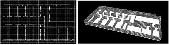
Fig. 2. The room in the editor window
The polyhedra assembled together form a closed space. To visualize polygons by finding intersection points of planes, polygons are constructed, which are displayed on the screen. All invisible external surfaces will be deleted later.
Fig. 3. Representation of a polyhedron in a file. 1 - Three points describing the plane. 2 - Additional information for visual presentation
When tracing rays, you will need to find the intersection of polygons and a ray. Of all the points of intersection, it will be necessary to choose the nearest one. Thus, for a ray, it is required to check for an intersection with each polyhedron for each reflection. This means that together with the complication of the shape of the room or its dimensions, the calculation time will also linearly grow. To get rid of this dependence, it is customary to build special accelerating structures that allow you to immediately drop large pieces of space when checking the intersection with the beam.
7. Building a field distribution
As a signal source, a point radiating uniformly in all directions is used. A random vector is chosen from the point and its intersection with the room is located. The resulting segment and the corresponding value of the field strength are stored in the list. From the end of the segment, the next ray is mirrored. The reflected vector can be constructed from the formula (single vectors):
where v - the incident vector, n - the normal of the surface.
The process continues for the required number of reflections and rays. When the calculation of the rays is completed, a grid is constructed with a resolution of 100x100x100, each segment of the rays adds its intensity value taking into account the traversed path at a fixed time point to those grid cells through which it passes [5] . The signal is harmonic. The resulting grid is displayed on the screen in the form of points - the larger the point, the greater the intensity (Figure 4).
Fig. 4. Results of calculations
Conclusion
In the course of the work, algorithms for modeling the propagation of radio waves in the room were studied and considered. The method of ray tracing from the transmitter to the surrounding space was used. In this case, the possibility of multipath signal propagation taking into account the reflection of radio waves from the elements of the room structure was taken into account. However, the following points were not taken into account in the work: