
- Introduction
- 1.Tasks and Tasks
- 2. Description of IoT from the point of view of IRS (info communications)
- 2.1 Features of the radio channel organization
- 2.1.2 Wireless Wi-Fi data transfer technology
- 2.1.3 ZigBee wireless data transmission technology
- 2.1.4 Bluetooth wireless technology BlueTooth
- Conclusions
- List of sources
Introduction
The Internet of Things [ 1 ] is the future technological revolution in the sphere of computing and communications, based on the concept of continuous and ubiquitous communication of any devices. Even at the present early stages of the Internet of things, the interaction between corporations, consumers and surrounding objects has changed. Technologies of the Internet of things have influenced such areas of decisions as intellectual power systems, supply chain management, reasonable cities and reasonable houses. The Internet of things is a paradigm of computing that will change business models, technology investments, customer service and everyday life. The Internet of Things is also a network of physical objects connected to the Internet, such as nanotechnology, consumer electronics, home appliances, all kinds of sensors, embedded systems and personal mobile devices. It involves network and communication technologies, such as IPv6, web services, radio frequency identification and 4G networks. We already apply in practice solutions based on the Internet of things when we use mobile devices. For example, you can monitor the security system, lighting, heating and air conditioning of your home on your smartphone. You can purchase a refrigerator that monitors your processes and sends reports to your smartphone. Industry forecasts suggest that by 2020, 50 billion devices can be combined. This is 10 times the number of all existing Internet hosts, including connected mobile phones. Such an amazing number of connected devices and the need for special conditions for support and effective management will lead to the emergence of complex and intricate tasks, from the decision of which the emergence and development of the Internet of things will depend.
1.Profits and tasks
The goal of this work is: to lower the level of economic costs by developing a methodology for organizing a radio channel of maximum range, taking into account the required parameters.
The main objectives of the study:
- Analysis of the component of the IoT service and identification of the cost part with the technical costs of the operator
- Analysis of the conditions for the organization of the radio channel
- Simulated channel simulation for conditions that take into account the proposed methodology
- Analysis of the economic efficiency of the proposed methodology
2. Description of IoT from the point of view of IKS (info communications)
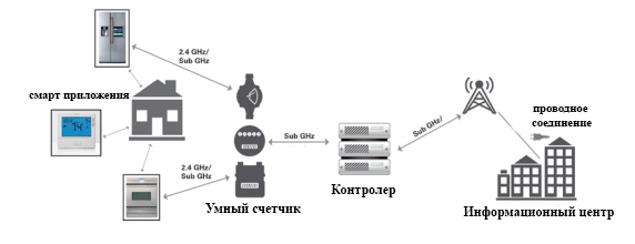
The network topology of the IoT system is based on simple nodes that collect and transfer a limited amount of information to a central controller or gateway that provides Internet connectivity and cloud services. Nodes and gateways should be designed in such a way as to minimize power consumption, provide reliable network connections and extend the range of wireless connectivity to the network as much as possible. The IoT system is based on a processor or microcontroller that processes data and runs software stacks that connect to a wireless device. The MCU and wireless device are specific to the end use and system requirements. Advanced IoT sensor nodes perform sensor functions and are used as an 8-bit microcontroller or 32-bit device to run a protocol stack of small radio frequency. These devices are usually battery-powered and connect to gateways where massive processing and data transfer occurs. Node sensors typically transmit small amounts of data and often perform battery operations for several years. These devices must also be portable, reliably connected and capable of operating under different environmental conditions, regardless of radio frequency interference or physical barriers. Since these devices are part of the network, the processing of sensor data and the display of information should also be considered. The combined selection of an appropriate MCU and wireless connection or connection to RF for these devices, as well as development tools and software stacks are critical to their successful creation.
2.1 Features of the organization of the radio channel
To organize a radio channel, to transmit information in the IoT environment, first of all, it is necessary to pay attention to the wireless method of data transmission, for this we compare the main technologies in order to obtain the most acceptable variant. Zigbee, Bluetooth, Wi-fi.
2. Description of IoT from the point of view of IKS (info communications)
The network topology of the IoT system is based on simple nodes that collect and transfer a limited amount of information to a central controller or gateway that provides Internet connectivity and cloud services. Nodes and gateways should be designed in such a way as to minimize power consumption, provide reliable network connections and extend the range of wireless connectivity to the network as much as possible. The IoT system is based on a processor or microcontroller that processes data and runs software stacks that connect to a wireless device. The MCU and wireless device are specific to the end use and system requirements. Advanced IoT sensor nodes perform sensor functions and are used as an 8-bit microcontroller or 32-bit device to run a protocol stack of small radio frequency. These devices are usually battery-powered and connect to gateways where massive processing and data transfer occurs. Node sensors typically transmit small amounts of data and often perform battery operations for several years. These devices must also be portable, reliably connected and capable of operating under different environmental conditions, regardless of radio frequency interference or physical barriers. Since these devices are part of the network, the processing of sensor data and the display of information should also be considered. The combined selection of an appropriate MCU and wireless connection or connection to RF for these devices, as well as development tools and software stacks are critical to their successful creation.
2.1.2 Wi-Fi Wireless Technology
The IEEE 802.11 standard is the basic standard for building Wireless Local Network (WLAN) [ 1 ]. The IEEE 802.11 standard has been constantly improved, and at the present time there is a whole family to which the IEEE 802.11 specifications with alphabetic indices a, b, c, d, e, g, h, i, j, k, l, m, n, o , p, q, r, s, u, v, w. However, only four of them (a, b, g and i) are basic and are most popular among equipment manufacturers, while the rest (c-f, h-n) are additions, improvements or corrections to accepted specifications. In its turn, the Institute of Electronics and Electrical Engineers (IEEE) only develops and accepts specifications, to the above standards. His duties do not include the testing of equipment from different manufacturers for compatibility. To promote the market for equipment for wireless local area networks (WLAN), a group was created, which was called the Alliance Wi-Fi. This alliance manages the work on certification of equipment from different manufacturers and issuing permission to use the Wi-Fi logo by members of the Wi-Fi Alliance. The presence on the equipment of the Wi-Fi logo guarantees reliable operation and compatibility of the equipment when building a wireless local area network (WLAN) on equipment of various manufacturers. Currently, Wi-Fi-compatible equipment is built on the standard IEEE 802.11a, b and g (can also use the standard IEEE 802.11i to provide a secure connection). In addition, the presence on the equipment of the Wi-Fi logo means that the equipment operates in the 2.4 GHz or 5 GHz band. Consequently, Wi-Fi should be understood as the compatibility of equipment of various manufacturers intended for building wireless LANs, taking into account the above limitations.
The original specification of the IEEE 802.11 standard, adopted in 1997, established data transmission at 1 and 2 Mbit / s in the unlicensed 2.4 GHz band, as well as a method for controlling access to a physical medium (radio channel) that uses the multiple Access with Carrier Sense Multiple Access with Collision Avoidance (CSMA-CA). The CSMA-CA method is as follows. To determine the state of the channel (busy or free), an algorithm is used to estimate the level of the signal in the channel, according to which the signal power at the receiver input and signal quality are measured. If the received signal power at the receiver input is below the threshold, then the channel is considered free, and if their power is above the threshold value, the channel is considered to be busy. After the adoption of the IEEE 802.11 specification, several manufacturers presented their equipment on the market. However, the equipment of the IEEE 802.11 standard was not widely used due to the fact that the standard specification did not uniquely define rules for the interaction of protocol stack levels. Therefore, each manufacturer presented its version of the implementation of the IEEE 802.11 standard, which is not compatible with the rest.
To remedy this situation in 1999, the IEEE adopts the first addition to the IEEE 802.11 specification called IEEE 802.11b. The IEEE 802.11b standard was the first standard for the construction of wireless local area networks, which has become widespread. The maximum data transfer speed in it is 11 Mbit / s. Such speed was possible to developers of the standard due to use of a method of coding by a sequence of additional codes (Complementary Code Keying). To control access to the radio channel, the same method is used as in the original specification of the IEEE 802.11-CSMA-CA standard. The above maximum data rate is, of course, a theoretical value, because the CSMACA method is used to access the radio channel, not guaranteeing the availability of a free channel at any one time. Therefore, in practice, when transmitting data over the TCP / IP protocol, the maximum throughput will be about 5.9 Mbps, and when using the UDP protocol, about 7.1 Mbps. In the event of a worsening of the electromagnetic environment, the equipment automatically reduces the transmission rate at the beginning to 5.5 Mbit / s, then to 2 Mbit / s, using the Adaptive Rate Selection (ARS) method. Decrease in speed allows for the use of simpler and less redundant coding methods, making the transmitted signals less prone to fading and distortion due to interference. Thanks to the adaptive speed selection method, IEEE 802.11b equipment can exchange data in different electromagnetic environments.
The next standard, added to the family of the IEEE 802.11 standard, is the IEEE 802.11a standard, the specification of which was adopted by the IEEE in 1999. The main difference between the specification of the IEEE 802.11a standard from the original specification of the IEEE 802.11 standard is as follows:
data transmission is carried out in the unlicensed frequency range 5 GHz;
orthogonal frequency modulation (OFDM) is used;
The maximum data transfer speed is 54 Mbit / s (the real speed is about 20 Mbit / s).
As in the 802.11b standard, 802.11a implements the Adaptive Rate Selection (ARS) method, which reduces the data transfer rate in the following sequence: 48, 36, 24, 18, 12, 9 and 6 Mbit / s. The information is transmitted via one of the 12 channels allocated in the 5 GHz band. The use of the 5 GHz band in the development of the 802.11a specification is primarily due to the fact that this range is less loaded than the 2.4 GHz band, and therefore the signals transmitted in it are less affected by interference. Undoubtedly, this fact is an advantage, but at the same time using the 5 GHz band leads to the fact that reliable operation of the equipment of the IEEE 802.11a standard is provided only in line of sight. Therefore, when building a wireless network, you need to install more access points, which in turn affects the cost of deploying the wireless network. In addition, signals transmitted in the 5 GHz band are more susceptible to absorption (the radiation power of the IEEE 802.11b and 802.11a equipment is the same).
The first samples of equipment standard IEEE 802.11a were introduced on the market in 2001. It should be noted that equipment that supports only the IEEE 802.11a standard has not been in great demand in the market for several reasons. First, at that time the equipment of the IEEE 802.11b standard already proved itself in the market, secondly, all noted the disadvantages of using the 5 GHz band and, thirdly, the equipment of the IEEE 802.11a standard is not compatible with IEEE 802.11b. However, subsequently manufacturers to promote IEEE 802.11a proposed devices that support both standards, as well as equipment that allows to adapt in networks built on equipment standard IEEE 802.11b, 802.11a, 802.11g. In 2003, the IEEE 802.11g standard specification was adopted, which establishes data transmission in the 2.4 GHz band at 54 Mbps (real speed is about 24.7 Mbps). To control access to the radio channel, the same method is used as in the original specification of the IEEE 802.11-CSMACA standard, as well as orthogonal frequency modulation (OFDM). Hardware standard IEEE 802.11g is fully compatible with 802.11b, however, due to the influence of interference, in most cases, the real data rate of 802.11g is comparable with the speed provided by equipment standard 802.11b. Therefore, the only correct solution for potential users of wireless LANs is the purchase of equipment that supports three standards at once: 802.11a, b and g. Wi-Fi-compatible equipment for most developers is associated primarily with the organization of access points for access to the Internet and with user equipment. It should be noted that the industry of embedded systems did not ignore the standards of IEEE 802.11a, b and g. Already, on this segment of the market there are offers that make it possible to make any device Wi-Fi-compatible. These are OEM modules of the IEEE 802.11b standard, which include: a transceiver, an application processing and execution processor. Thus, these modules represent a completely complete solution, which allows to significantly reduce the time and cost of implementing the Wi-Fi-compatibility of the product being developed. In general, OEM modules of the IEEE 802.11b standard are integrated into products for remote monitoring and control over the Internet. To connect the OEM module of the IEEE 802.11b standard to the product, a serial RS-232 interface is used, and the module is controlled by AT-commands. The maximum distance between the OEM module of the IEEE 802.11b standard and the access point using a special remote antenna can be up to 500 m. The maximum distance does not exceed 100 m in the premises, and in the presence of line of sight it increases to 300 m. A significant drawback of such OEM modules is their high price.
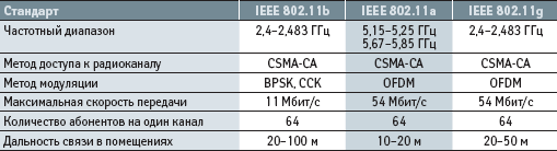
Table 1 lists the main technical characteristics of the IEEE 802.11a, b and g standards.
2.1.3 ZigBee wireless data transmission technology
ZigBee's wireless data transmission technology was introduced on the market after the introduction of wireless data transmission technologies BlueTooth and Wi-Fi. The appearance of ZigBee technology is primarily due to the fact that for some applications (for example, for remote control of lighting or garage gates or for reading information from sensors), the main criteria for choosing a wireless transmission technology is low power consumption of the hardware and its low cost. This implies low bandwidth, since in most cases the sensors are powered by the built-in battery, the operating time from which should exceed several months and even years. Otherwise, a monthly battery replacement for the garage door open and close sensor will dramatically change the user's attitude to wireless technologies. The current technologies for wireless data transmission BlueTooth and Wi-Fi did not meet these criteria, providing data transmission at high speeds, with a high level of power consumption and hardware costs. In 2001, the working group No. 4 of IEEE 802.15 started work on the creation of a new standard that would meet the following requirements:
very low power consumption of hardware that implements wireless data transmission technology (battery life should be from several months to several years)
The transfer of information should be carried out at a low speed
low cost of hardware.
The result was the development of the IEEE 802.15.4 standard. Many publications under the IEEE 802.15.4 standard understand ZigBee technology and vice versa under ZigBee - IEEE 802.15.4 standard. However, it is not. In Fig. 5 shows the interaction model of the IEEE 802.15.4 standard, the wireless technology of ZigBee data transfer and the end user.
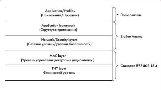
Fig. 1. Interaction model of the IEEE 802.15.4 standard, wireless technologies for ZigBee and end-user data transfer
The IEEE 802.15.4 standard [ 3 ] specifies the interaction of only the two lowest layers of the interaction model: the physical layer (PHY) and the access control level for the radio channel for the three unlicensed frequency bands: 2.4 GHz, 868 MHz and 915 MHz. Table 2 shows the main characteristics of equipment operating in these frequency bands.
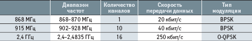
Table 2. Basic Equipment Characteristics
The MAC layer is responsible for controlling access to the radio channel using the Carrier Sense Multiple Access with Collision Avoidance (CSMA-CA) method, as well as controlling connection and disconnecting from the data network and providing protection transmitted information by a symmetric key (AES-128). In turn, the ZigBee wireless data transmission technology offered by the ZigBee alliance defines the remaining layers of the interaction model, which include the network layer, security level, application structure level and application profile layer. The network layer, ZigBee's wireless data transmission technology, is responsible for device discovery and network configuration and supports the three network topology options shown in Fig. 2.
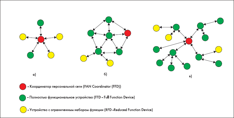
Fig. 2. Three variants of the network topology
To ensure the low cost of integrating ZigBee wireless technology into various applications, the physical implementation of the IEEE 802.15.4 hardware is performed in two versions: devices with a limited function set (RFD) and fully functional devices (FFDs). When implementing one of the network topologies shown in Fig. 6, requires the presence of at least one FFD device that acts as a network coordinator. Table 3 lists the functions performed by the FFD and RFD devices.
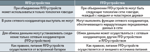
Table 3. List of functions performed by FFD and RFD devices
The low cost of the hardware of RFD devices [ 4 ] is provided by limiting the set of functions when interacting with a network coordinator or an FFD device. This, in turn, affects the incomplete implementation of the interaction model shown in Fig. 1, and also imposes minimal requirements on memory resources. In addition to dividing devices into RFD and FFD, the ZigBee alliance defines three types of logical devices: the ZigBee coordinator, the ZigBee router and the ZigBee terminal. The coordinator performs network initialization, node management, and stores information about the settings of each node connected to the network. The ZigBee router is responsible for routing messages transmitted over the network from one node to another. A terminal device is any terminal device connected to the network. The RFD and FFD devices discussed above are just terminal devices. The type of logical device in the construction of the network is determined by the end user by selecting a specific profile (Figure 1), proposed by the ZigBee Alliance. When building a network with the topology "each with each", the transmission of messages from one node of the network to another can be carried out on different routes, which makes it possible to build distributed networks (combining several small networks into one large cluster tree) with the installation of one node from another on a sufficiently large distance and ensure reliable delivery of messages.
Traffic transmitted over the network ZigBee, as a rule, is divided into periodic, intermittent and repetitive (characterized by a small time interval between sending messages). Periodic traffic is typical for applications that need to remotely receive information, for example from wireless sensor sensors or meters. In such applications, the acquisition of information from sensors or counters is carried out as follows. As mentioned earlier, any terminal device, in which the wireless sensor acts as the example, the overwhelming part of the operating time should be in the "sleep" mode, thus providing very low power consumption. To transfer information, the terminal at certain points in time leaves the sleep mode and searches the radio for a special signal (beacon) transmitted by the network management device (ZigBee coordinator or ZigBee router) to which the wireless counter is connected. If there is a special signal (beacon) in the air, the terminal device transmits information to the network management device and immediately switches to the "sleep" mode until the next communication session. Intermittent traffic is inherent, for example, for remote lighting control devices. Let's imagine the situation when it is necessary to send a command to turn on the lighting in the hall when the motion sensor installed at the entrance door is triggered. The transfer of the command in this case is carried out as follows. When the network management device receives a signal from the motion sensor, it issues a command to the terminal device (wireless switch) to connect to the ZigBee wireless network. Then, the connection to the terminal device (wireless switch) is established and the information message containing the command to turn on the lighting is transmitted. After receiving the command, the connection is disconnected and the wireless switch is disconnected from the ZigBee network.
Connecting and disconnecting the terminal device to the ZigBee network only at the necessary moments allows to significantly increase the time of the end device stay in the "sleep" mode, thus ensuring minimum power consumption. The method of using a special signal (beacon) is much more energy-intensive. In some applications, such as security systems, the transmission of information about the operation of sensors should be carried out almost instantaneously and without delay. But we must take into account the fact that at some point in time several sensors can "work", generating a so-called repeating traffic on the network. The probability of this event is small, but it is inadmissible to not take it into account in security systems. In the ZigBee wireless network, messages sent to the wireless network when several security sensors (endpoints) are triggered are transmitted from each sensor in a dedicated time slot. In ZigBee technology, a specially allocated time slot is called a guaranteed time slot (Guaranteed Time Slot, GTS). The availability in ZigBee technology of the ability to provide a guaranteed time slot for the transmission of urgent messages makes it possible to talk about the implementation of QoS (quality of service) in ZigBee. The allocation of the guaranteed time slot for the transmission of urgent messages is carried out by the network coordinator (Figure 3, PAN Coordinator).
In developing the hardware of ZigBee's wireless data transmission technology, which implements the interaction model, virtually all manufacturers adhere to the concept that all hardware is placed on a single chip. In Fig. 3 shows the concept of the execution of the hardware part of ZigBee wireless data transmission technology.
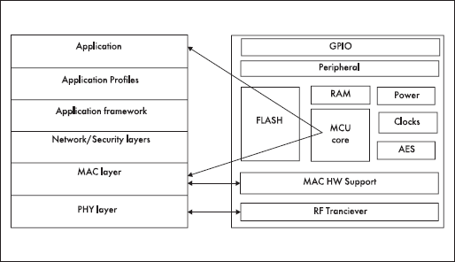
Fig. 3. The concept of the execution of the hardware part of ZigBee wireless data transmission technology
To build a wireless network (for example, a network with a star topology) based on ZigBee technology, the developer must purchase at least one network coordinator and the required number of endpoints. When planning the network, it should be taken into account that the maximum number of active terminals connected to the network coordinator should not exceed 240. In addition, you need to purchase from the manufacturer of ZigBee chips software tools for developing, configuring the network and creating custom applications and profiles. Almost all manufacturers of ZigBee-chips offer a whole line of products on the market, differing, as a rule, only by the amount of ROM and RAM. For example, a chip with 128 KB of ROM and 8 KB of RAM can be programmed to work as a coordinator, router and endpoint. The high cost of the debugging kit, which includes a set of software and hardware for building ZigBee wireless networks of any complexity, is one of the limiting factors in the mass distribution of ZigBee technology on the Russian market. It should be noted that the emergence of wireless transmission technology ZigBee has become a definite response to the needs of the market for the creation of intelligent control systems for private houses and buildings, the demand for which is increasing every year. In the near future, private houses and buildings will be equipped with a huge number of wireless network nodes that monitor and manage life support systems at home. Installation of these systems can be done at any time and in a short time, as it does not require wiring in the building cables.
We list the applications in which ZigBee technology can be integrated:
Automation systems for life support of houses and buildings (remote control of network outlets, switches, rheostats, etc.)
Control systems for consumer electronics
Automatic reading systems from various meters (gas, water, electricity, etc.)
Safety systems (smoke detectors, access and protection sensors, gas leakage sensors, water sensors, etc.)
Environmental monitoring systems (temperature sensors, d humidity, vibration, etc.)
Industrial automation systems
2.1.4 Wireless transmission technology BlueTooth
Technology BlueTooth (the standard IEEE 802.15) was the first technology that allows to organize a wireless personal data network (WPAN - Wireless Personal Network). It allows data and voice to be transmitted over the radio channel for short distances (10-100 m) in the unlicensed frequency range of 2.4 GHz and connect PCs, mobile phones and other devices in the absence of direct visibility. The birth of BlueTooth is due to Ericsson, which in 1994 began developing a new communication technology. Initially, the main goal was to develop a radio interface with low power consumption and low cost, which would allow communication between cellular phones and wireless headsets. However, subsequently the work on the development of the radio interface has smoothly evolved into the creation of a new technology.
On the telecommunications market, as well as on the computer market, the success of new technology is provided by leading manufacturing companies that decide on the feasibility and economic benefits of integrating the new technology into their new developments. Therefore, in order to provide its offspring with a decent future and further development, in 1998, Ericsson organized the BlueTooth SIG (Spesial Interest Group) consortium, which faced the following tasks:
further development of BlueTooth technology
promotion of new technology in the telecommunications market
The BlueTooth SIG consortium [ 5 ] includes such companies as Ericsson, Nokia, 3COM, Intel, National Semiconductor. It would be logical to assume that the first steps taken by the BlueTooth SIG consortium will be to standardize the new technology for the compatibility of BlueTooth devices developed by different companies. This was implemented. To this end, specifications have been developed that describe in detail the methods of using the new standard and the characteristics of data transfer protocols.
As a result, the BlueTooth wireless protocol stack was developed (Fig. 4).
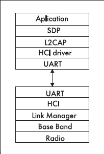
Fig. 4. The Bluetooth protocol stack
BlueTooth technology supports both point-to-point and point-to-multipoint connections. Two or more devices using the same channel form a piconet (piconet). One of the devices works as a master, and the others work as slaves. One piconet can have up to seven active slave devices, while the other slave devices are in the "parking" state, remaining synchronized with the main device. Interacting piconet form a "distributed network" (scatternet). Each piconet has only one primary device, but slave devices can enter different piconets. In addition, the basic device of one piconet may be subordinate to another (Figure 5).
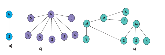
Fig. 5. Piconet with subordinate devices. a) with one slave. b) several. c) Distributed network
Since the first BlueTooth modules appeared on the market, the complex implementation of the BlueTooth protocol stack prevented their wide application in new applications. The developer had to independently implement the BlueTooth module control and develop profiles that determine how the module interacts with other BlueTooth devices using the Host Controller Interface (HCI) commands. Interest in BlueTooth technology grew every day, more and more companies appeared, developing components for it, but there was no solution that would greatly simplify the management of BlueTooth-modules. And such a decision was found. The Finnish company, having studied the situation on the market, was one of the first companies to offer the following solution. In most cases, BlueTooth technology is used by developers to replace a wired serial connection between two devices by a wireless one. To make a connection and perform data transfer, the developer needs to implement the upper levels of the BlueTooth protocol stack using the commands of the host controller interface, which include: L2CAP, RFCOMM, SDP, as well as the SPP (Serial Port Profi le) and an SDP service discovery profile (Service Discovery Profile). This is what the Finnish company decided to play by developing a BlueTooth module firmware version that represents the complete software implementation of the entire BlueTooth protocol stack (Figure 1), as well as the SPP and SDP profiles. This solution allows the developer to manage the module, establish a wireless serial connection and perform data transfer using special character commands, in the same way as when working with conventional modems through standard AT commands.
At first glance, the above solution significantly reduces the integration time of BlueTooth technology into newly developed products. However, this imposes certain limitations on the use of the capabilities of the BlueTooth technology. Basically, this affects the reduction in the maximum throughput and the number of simultaneous asynchronous connections supported by the BlueTooth module.
In mid-2004, BlueTooth specification version 1.1, which was published in 2001, adopted the BlueTooth version 1.2 . The main differences between specification 1.2 and 1.1 are: 1. Realization of Adaptive Friquency hopping (AFH) technology.
2. Improvement of voice connection. Page 3. Reduces the time it takes to establish a connection between two BlueTooth modules.
It is known that BlueTooth and Wi-Fi use the same unlicensed band of 2.4 GHz. Therefore, in cases where BlueTooth devices are in the range of Wi-Fi devices and communicate with each other, this can lead to collisions and affect the performance of devices. AFH technology avoids the appearance of collisions: during the exchange of information to combat interference, BlueTooth technology uses a channel hopping, which does not take into account the frequency channels on which Wi-Fi data is exchanged. In Fig. Figure 6 illustrates the principle of the AFH technology
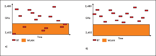
Fig. 6. The principle of AFH technology. a) collisions b) escape from collisions with adaptive channel frequency tuning
Currently, there are a large number of companies offering BlueTooth modules on the market, as well as components for self-implementation of the hardware of the BlueTooth device. Almost all manufacturers offer modules supporting BlueTooth versions 1.1 and 1.2 and corresponding to class 2 (10 m range) and class 1 (range 100 m). However, despite the fact that version 1.1 is fully compatible with 1.2, all the improvements mentioned above, implemented in version 1.2, can be obtained only if both devices comply with version 1.2. In November 2004, BlueTooth specification version 2.0 [ 6 ] was adopted, which supports Enhanced Data Rate (EDR) technology. Specification 2.0 with EDR support allows data exchange at speeds up to 3 Mb / s. The first commercially available sample modules, corresponding to version 2.0 and supporting EDR extended data transfer technology, were offered by manufacturers in late 2005. The radius of action of such modules is 10 m in the absence of line of sight, which corresponds to class 2, and in the presence of line of sight it can reach 30 m.
As noted earlier, the main purpose of the technology BlueTooth - the replacement of a wired serial connection. However, the SPP profile [ 7 ] used to organize the connection is certainly not the only profile that developers can use in their products. The BlueTooth technology defines the following profiles: the Generic Access Profile, the Service Discovery Profile, the Cordless Telephony Profile, the Intercom Profile, the Wireless Headset Profile Profile, Dial-up Networking Profile, Fax Profile, Lan Access Profile, Generic Object Exchange, Profile Object Push Profile, the file transfer profile (File Transfer Profile), the synchronization profile and (Synchronization Profile).
Summarizing on the choice of technology for wireless data transmission, we give in the table the brief characteristics of the options considered.Conclusion
Summarizing the choice of technology for wireless data transmission, we give in the table the brief characteristics of the options considered.
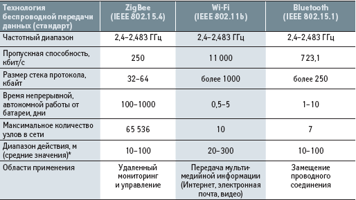
Table 4. Comparative characteristics of BlueTooth, Wi-Fi and ZigBee technologies
Based on the above data, for wireless transmission of information, it will be advisable to choose the technology of Wi-FI because, it has the greatest range of action, namely, 20-300, the highest throughput 11 000, as well as the possibility of transferring multimedia information.
Note
At the time of writing this essay, the master's work is not yet complete. Estimated completion date: May 2018. Full text of the work, as well as materials on the topic can be obtained from the author or his supervisor after the specified date.
Список источников
- Технологии беспроводной передачи данных ZigBee, BlueTooth, Wi-Fi.[Электронный ресурс] : http://wireless-e.ru/....
- Internet of Things.[Электронный ресурс] : https://www.redbooks.ibm.com/...
- Управление доступом к среде.Википедия[Электронный ресурс] : https://ru.wikipedia.org/wiki/...
- RFID-технология. Все о радиочастотной идентификации.[Электронный ресурс] : http://www.rst-invent.ru/...
- BLUETOOTH SIG: НАСТОЯЩИЙ ИНТЕРНЕТ ВЕЩЕЙ НА ОСНОВЕ BLE – ВОПРОС БЛИЖАЙШЕГО ВРЕМЕНИ.[Электронный ресурс] : https://www.gadgetstyle.com.ua/...
- Bluetooth-2.0 + EDR: первое впечатление.[Электронный ресурс] : https://itc.ua/...
- Национальная библиотека им. Н. Э. Баумана Bauman National Library.[Электронный ресурс] : https://ru.bmstu.wiki/...