
Abstract
Contents
- Introduction
- 1.Theme urgency
- 2.Goal and tasks of the research
- 3.Review of research and development
- 3.1 Justification of the accepted direction of the ACS development by the water supply unit
- 3.2 The model of ACS level in pure water tanks
- 3.3 Synthesis of ACS by the pressure of the pumping unit
- Conclusion
- References
Introduction
As a supplier of water to almost 50% of the world's population, water utilities play a vital role in the water management process, which has been increasingly the subject of acute shortages. Now, when the process of global urbanization continues, the water supply system faces the complex task of water supply of the city in an economically efficient way to ensure their normal life.
Over the past decade, the deterioration of the existing water supply system has become more and more noticeable, which is accompanied by an increase in the frequency of breakthroughs of both major main and small supply pipelines. The lack of means to monitor water consumption and means of operative influence on the productivity of pumping stations leads to unsatisfactory water supply to end users and increases emergency situations in the system.
1. Theme urgency
A distinctive feature of the water supply system is an almost random change in the load on the network - the magnitude of water consumption. For each individual system, an approximate daily consumption schedule is known, but it allows one to adhere only to a certain average water supply, which, as a rule, does not correspond to actual water consumption. In this case, pressure fluctuations occur in the system's backbones. Increased pressure leads to pipeline ruptures and reduced service life of shut-off valves, as well as a reduction in the amount of water supplied to high-altitude consumers and a deterioration in the quality of water supply in general.
Thus, the problem of improving the quality of water supply is relevant. At the same time, with the increase in energy prices, it becomes an urgent problem to reduce the cost of electricity consumed by the nodes of the water supply complex.
To solve these problems, it is possible to perform automation of the whole water supply system in order to ensure the required water supply at the required pressure and its absence of oscillations using energy-saving approaches to building an automatic control system.
Important factors contributing to the economy and reliability of the water supply system are the automation of production processes. Automatic control of the water supply unit makes it possible to improve and streamline the operation of both its individual components and the entire system as a whole, significantly reduce the number of maintenance personnel, substantially reduce operating costs and increase the quality of the services provided. For example, a comparison of water costs in different parts of the water supply system allows to identify the places of leaks, high resistance within the pipes and form the requirements for water supply in real time. Controlling the water pressure makes it possible to eliminate excess water supply. Measuring the input power of the motor and measuring the speed of the pump can determine whether the motor is operating at the optimum efficiency and, if necessary, it is corrected [1].
2. Goal and tasks of the research
The purpose of the development is to increase the efficiency of the water supply unit by developing an automatic control system that will extend the life of the process equipment, increase efficiency, reliability and safety, and also reduce operating costs for the water supply process.
Methods and means of development: methods of system analysis and decomposition, theory of automatic control, computer simulation, analysis of experimental results.
According to the available technological scheme of the district water supply complex and the values ??of the necessary technological parameters, the following requirements are formulated for individual nodes and the complex as a whole:
- Ensuring that the level in clean water reservoirs is maintained between 2 m and 4.5 m to exclude cavitation modes of the water supply pump and avoid water overflows when reservoirs are full.
- Provide pressure on the "upper zone" and "bottom zone" combs at 7 and 4 atm, respectively, with any amount of water consumption.
- Provision of pressures by raising stations of 7 atm for the "upper zone" and 4 for the "lower zone" with any amount of water consumption.
- Ensure the absence of water hammering in the water supply system.
- Absence of vacuum in the suction pipelines of the raising stations [2].
3. Review of research and development
The water supply unit includes a chlorination unit, two clean water reservoirs with a volume of 10,000 m3, a pumping station of the II lifting with two pressure zones - 4 atm and 7 atm, and the number of output conduits 3 and 5, respectively, for each of the zones. One of the lower zone water conduits has a raising station at a distance of 20 km from the water supply unit, two water conduits of the upper zone have one raising station at a distance of 1.5 km and 4 km from the water supply unit. The pumping of water after the pumping station II of the lift is carried out without the use of intermediate tanks. Water is supplied to the water supply unit through two water conduits with diameters of 1000 mm and 700 mm.
The analysis of this control object allowed to formulate requirements for individual nodes and a complex of water supply in general, the main ones of which are as follows: maintenance of maintaining a level in clean water tanks in the range from 2 m to 4.5 m; providing pressures at the outlet of the "upper zone" and "lower zone" pumps at 7 and 4 atm, respectively, at any quantity of water consumption [3].
The water supply system of the Proletarsky district of the city of Donetsk consists of the water supply unit "6 Krasnaya Zvezda" and three pumping stations.
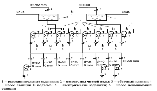
Figure 1 - Technological scheme of water supply
3.1 Justification of the accepted direction of the ACS development by the water supply unit
For centrifugal pump installations, the following methods for controlling the pressure (head) and flow (capacity) of the liquid are used: throttling of the pressure pipeline; a part of the flow of liquid from the outlet of the pump in the inlet; disconnection or connection of pumps (step regulation); changing the speed of the pump impeller [4].
The control of the head by bypass is based on the drainage of a part of the flow of liquid from the pump outlet to its inlet through a branch with a gate. At the same time, the energy expended on the circulation of the liquid along the idle wheel does not create useful work, reduces the efficiency of the installation, especially when deep regulation is used. As in the previous method, the supply of the pumping station is only adjusted downwards.
The stepwise regulation of the pump station is accomplished by connecting or disconnecting a pump or a group of pumps. This method is characterized by simple control, since it does not require additional control devices. However, it does not allow to provide continuous and high-quality support of the head when changing fluid intake and causes frequent engine starts, shortens the equipment life and requires the construction of an intermediate reservoir, to smooth the fluctuations in the supply of the pumping station. In addition, the electric drives do not work in the optimal mode, which also reduces the efficiency of the entire station [5].
Changing the rotational speed of the impeller of the pumping unit allows for continuous control of the pumping station's performance with less energy than in the previous versions, it is possible to achieve a smooth increase in capacity to the nominal value. However, it requires relatively high costs for regulating equipment [6].
Water flow sensors are installed on the supply and discharge water conduits, as well as at the output of each pump; level sensor - in clean water tanks; pressure sensors - at the inlet and outlet of each pump of the second lifting pumping station.
The actuators are the electric actuators of the valves (level control in clean water tanks and pressure in the discharge conduits), as well as the electric drive of the pump (pressure control of the pumping unit).
The control of the electric drive of the valves can be realized with the help of frequency converters, i.e. to carry out frequency regulation. The control of the valve will be reduced to feeding the motor for a certain time of setting the voltage of a certain frequency, calculated by the microcontroller and depending on the flow in the inlet water conduit, the outlet water conduits, the fullness of the RF [7].
The foregoing allows us to develop schemes for automatic control of elements of the water supply unit, which are shown in Fig. 2 and Fig. 3.
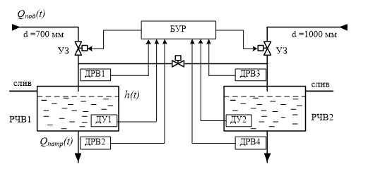
Figure 2 - Automatic control of clean water tanks
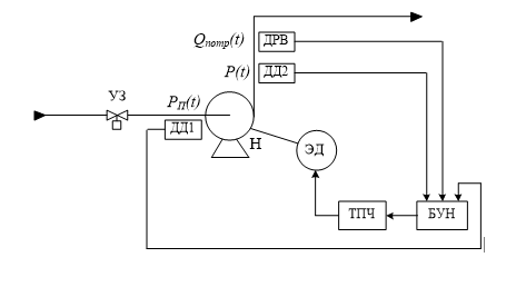
Figure 3 - Automatic control of the pumping unit
3.2 The model of ACS level in pure water tanks
To determine the necessary algorithms, mathematical models for various control loops have been developed. The structural diagram of the ACS level in the clean water reservoirs of the "6 Red Star" water supply unit, which is shown in Fig. 4, is obtained.
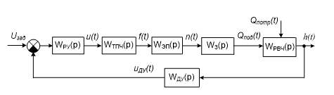
Figure 4 - Structural diagram of the ACS level in clean water tanks
The control object in this automatic control system is a pure water tank WRF (p) with the following variables:
- output control variable - level h (t);
- control action - flow rate of supply water Qp (t);
- disturbance - consumption of consumed water Qpot (t) [8].
The water level in the tanks is controlled, controlled and determined by the formula:
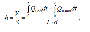
Where V is the volume of liquid in the tank; S is the bottom area of the tank; Qpod - water supply to the tank; Qpot - consumption of water from the reservoir.
Connecting the subsystems according to the structural scheme (Fig. 4), we obtain the model of the ACS level in terms of the simulink package (Fig. 5).
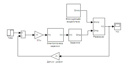
Figure 5 - Model ACS level in the tank in terms of the package sіmulіnk
3.3 Synthesis of ACS by the pressure of the pumping unit
The pumping unit is an object with self-leveling without delay. According to the theory of automatic control for these objects, it is possible to apply all standard control laws. Selection and adjustment of standard regulators is carried out using the developed model of a closed automatic control system with the pressure of a pumping unit with a typical regulator, the circuit of which is shown in Fig. 5 [9].
Typical control laws that are implemented by the appropriate regulators are the most widespread in the management of various objects: the P-regulator, the PI controller, the PID controller.
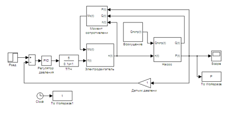
Figure 6 - The model of ACS by the pressure of a pumping unit with a regulator
Analysis of the transient curve (Fig. 6) shows inadmissible overshoot, oscillation and steady-state error through the reference and disturbance channels, therefore more complex control algorithms are needed [10].
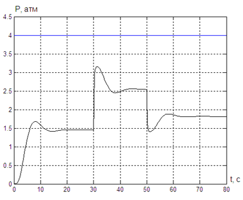
Figure 7 - Pressure change when used in the AC of a P regulator
The curve of the transient process in the ACS by the pressure of the pumping unit with the calculated PI regulator is shown in Fig. 8.
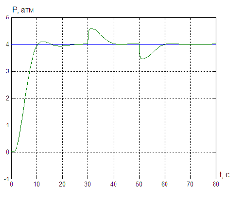
Figure 8 - Pressure change when used in the AC PI regulator

Figure 9 - Pressure change when used in the PID controllers
Analysis of the given curves of the transient processes along the channels of the task and the disturbance (Fig. 9.) shows their full compliance with the regulatory requirements: the steady-state value of the error signal along the reference and disturbance channels is zero, the initial deviation of the controlled value from the set value through the disturbance channel is not more than required.
Thus, from the considered typical regulatory laws fully meets the requirements of regulatory documents and the technological regulations of the automatic control system with the pressure of a pumping unit with a PID regulator.
Conclusion
In the master's thesis, a system of automatic control of the water supply unit "6 Red Star" was developed.
The analysis of the elements of the water supply complex of the region and their interaction made it possible to establish the features of the water supply unit as a control object.
In the Bachelor's thesis, schemes of automatic control of the technological elements of the water supply unit - clean water tanks and pumping units, on the basis of which the elements of the automatic control system are selected.
The theoretical synthesis of the required ACS regulators in the level of pure water tanks and automatic control systems by the pressure of the pumping unit was performed in the work. It is shown that the required quality control in the automatic control system is achieved by using a combined automatic control system: with a PD controller in the feedback loop and with a P-regulator in the compensation circuit of the disturbing effect.
The performed comparative analysis of the quality indicators in the automatic control system by the pressure of the pumping unit using various standard control laws showed that the best regulator in this case is the PID controller with the settings found.
The simulation performed in the work confirmed the effectiveness of the proposed control algorithms and the adopted technical solutions.
References
- Somov MA Water supply systems and facilities. Textbook. for universities. Moscow: Stroiizdat, 1988 - 399 p.
- Zhurba MG, Sokolov LI, Govorova Zh.M. Water supply. Design of systems and structures. Volume 3. Water distribution and supply systems. Moscow: Publisher ASV, 2004 - 256 p.
- Turk VI, Minaev AV, Karelin V.Ya. Pumps and pump stations. M.: Stroiizdat, 1976.-304 p.
- Cherkassky VM Pumps, fans, compressors: Textbook for high schools. - M: Energoatomizdat, 1984. - 316 p.
- Gustav Olson, Jangguido Piani Digital automation and control systems. St. Petersburg, 2001. - 557 p.
- Geyer VG, Timoshenko G.М. Mine fan and drainage installations. M .: Nedra, 1987. - 270 with.
- Popov V.M. Mine drainage installations. - 2 nd ed., Pererab. and additional. - Moscow: Nedra, 1983. - 304 p.
- Popov V. M. Mine pumps (theory, calculation and operation). - Moscow: Nedra, 1993. - 224 p.
- Zaitsev G.F. Theory of automatic control and regulation. Kiev: Vishcha school, 1988 - 431 p.
- Lucas VA The theory of control of technical systems. A compact training course for universities - 3rd ed. Pererab. and additional. - Ekaterinburg, UGGAA, 2002. - 675 pp. .