
Abstract
Content
- Introduction
- Analysis of the object of study
- 1. General principles of construction of electrotechnical
- 1.1 Complete transformer substations
- Conclusions and Objectives
- List of sources
Introduction
Mining is a complex of interrelated energy-intensive technological processes and presupposes the use of high-power electromechanical equipment in conditions of potential fire hazard, explosion of methane-air mixture or coal dust. The risk factors are supplemented with a high degree of probability of mechanical damage to the flexible cables of the local power grids, which are used to supply electric power from the district distribution points to the consumers' electric motors. As a result of such damages, states of interphase short circuits accompanied by ignition of electrical equipment may occur; danger of electroporation of the person at a contact of the phase conductor which is under pressure
These circumstances necessitate the application of a whole complex of measures for the protective de-energization of mine electrotechnical complexes in the event of emergency or emergency conditions, which is realized by appropriate automatic means of protection.
Analysis of the object of study
1. General principles of construction of the electrotechnical complex
The process of coal mining in a modern mining enterprise takes place under the condition of functioning of numerous technological installations: treatment and preparatory complexes, conveyor and locomotive transport, dewatering, ventilation, mine lifting, etc. All these units are equipped with electric drives, usually medium or high power. So, the electrotechnical complexes of the technological sections and installations of the mine are its most important objects, ensuring the fulfillment of all production processes.
The structure of the electrotechnical complex of the mining section of the mine, shown in Figure 1.2, is constructed in accordance with the provisions of regulatory documents and contains a power source - a complete transformer substation, distribution points and asynchronous electric motors (M) of consumers. In turn, the district distribution center should be represented by a set of magnetic starters (P), from which a branched network of flexible cables (HA) flows through the radial scheme to the asynchronous motors of the respective consumers. [1]
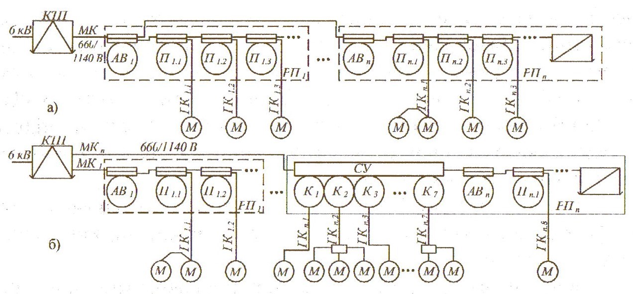
Figure 1.2 - Typical scheme of power supply to the mine mining site based on the application of starters (a) control stations (b)
A group circuit-breaker is used at the input of a local distribution point with the purpose of supplying (removing) the voltage at the distribution point manually and switching it off in automatic mode when the mains voltage disappears, a short-circuit in the branch occurs, or an external process protection command is present (for example, gas protection ). The supply of voltage from the station substation to the input of the group circuit-breaker of the distribution point takes place via a trunk cable, which accepts armored or semi-flexible shielded cables.
Along with the use of magnetic starters, the entire set of power switching devices of the distribution point of the section can be located in a complete switchgear - the control station in accordance with Figure 1.3.
Modern trends in the use of high-power energy equipment necessitate the power supply of such consumers with a voltage of an elevated nominal level (1140 V). As a rule, the peculiarity of the circuit arrangement for power supply of mine sites is that the power supply is used only for powerful current collectors (harvester, conveyor), and other low-power consumers connect to a line voltage of 660 V in accordance with Figure 1.4
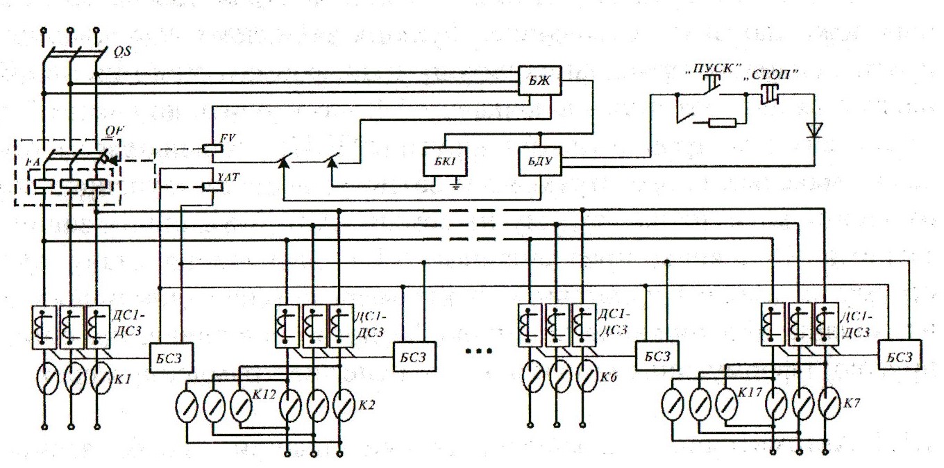
Figure 1.3 - Generalized structural diagram of a control station of the SUV-350A type (SUV-630)
In accordance with Figure 1.3, the generalized structural diagram of the control station of the SUV-350A consists of the following parts:
- БП - power supply;
- БГУ - remote control unit;
- БКИ - isolation control unit
- БСЗ - current protection unit
- ДС1- ДСЗ - current sensors;
- QS - disconnector;
- QF - circuit breaker;
- FA1 - electromagnetic release;
- FV- zero release;
- YАТ- independent release:
- К1-К7 - contactors of outgoing connections
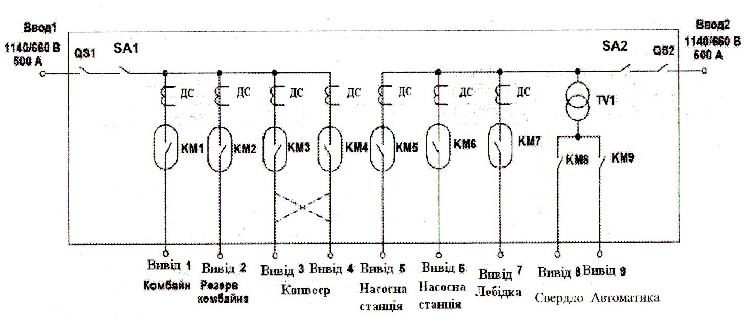
Figure 1.4 - Block-structure diagram of the complete control device KUUV-500 / 500-2 (provision of power supply to consumers sections with voltages of two nominal levels - 660 V and 1140 V)
So, the power supply source for the consumers of the technological section is the complete transformer substation, indicated in Figure 1.5, which performs the function of converting the high voltage (6 kV) into a voltage coordinated in terms of the level with the nominal voltage of the consumers sections (660 V or 1140 V). The neutral mode of the grid power grid of the mine is isolated. The function of the residual voltage protection from the power connection of the output of the transformer substation is realized by the circuit-breaker 8A, which is part of its low-voltage switchgear and operates under the command of the overcurrent protection; the apparatus for the protective de-energization of the earth leakage current circle, and other external protections. The main purpose of automatic protection is to determine the state of leakage of the current to the ground in the local power grid (due to damage to the insulation, or the person touching the live conductor under voltage) and forming a command to protect the mains. [2]
1.1 Complete transformer substations
Voltage transformers are used to convert an AC voltage of one level into an alternating current voltage of another level of the same frequency.
Two-winding transformers with a primary voltage of 35-115 kV and a secondary 6.3-6.6 kV are used to supply the mines with natural oil cooling or with blowing and natural circulation of oil. Transformers can be equipped with devices for voltage regulation under load. For power supply of low-voltage consumers, two-winding transformers with oil cooling are used, with a higher voltage of 6 kV and a lower voltage of 0.23; 0.4; 0.69 kV with a power from 25 kVA to 1600 kVA. For mines with a separate power supply, three-winding transformers with oil cooling and voltage regulation under load with capacity from 10,000 kVA to 40000 kVA are used, shown in Figure 6.1. The secondary winding of the three-winding transformer TDTNS with a voltage of 6.3 kV is used to power the surface consumers, and the 6.6 kV winding is used to power underground consumers. The use of three-winding transformers in the structure of the main surface substations of mines allows galvanic separation of surface and underground power supply networks. As a result, these networks can have a different neutral mode. Insulation resistance of the surface and underground electrical networks are not galvanically interconnected and do not influence each other (as a parallel connection of resistances). Various kinds of overvoltages arising in the electric network of the surface, to a lesser extent, affect the parameters of the underground electric grid of the mine.
Currently, in the scheme of the main surface substations of mines equipped with two-winding transformers initially, for the purpose of galvanic isolation of underground and surface electric networks, there are additionally provided separating two-winding transformers with a ratio of 1: 1 TMSH transformer, power from 2500 to 4000 kVA.
Oil-cooled transformers are supplied with gas relays to protect against excessive temperature rise inside the transformer and oil leakage, as well as thermosiphon filters 5 for continuous oil regeneration.
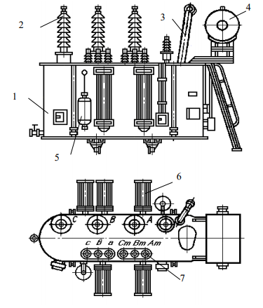
Figure 6.1 - Three-winding transformer TDTNSH: 1 - a tank; 2 - high voltage input device; 3 - an exhaust pipe; 4 - expansion tank; 5 - the filter; 6 - radiator; 7 - low voltage input device.
For the electrical supply of relocated electrical installations, as well as for the electrical supply of electrical installations with a limited duration of use, complete transformer substations with a voltage of 35/6 kV with the power of 1000 ... 6300 kVA are used. They can be block type and transportable. To supply low-voltage consumers, they manufacture complex transformer substations for indoor and outdoor installations. Complex transformer substations provide reception, transformation and distribution of electric energy. The complex transformer substations consist, shown in figure 6.2 from the input complete switchgear of the higher voltage 1, the transformer 2 and the switchgear of the lower voltage 3.
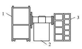
Figure 6.2 - Typical layout of a package transformer substation
In accordance with Figure 1.5, the functional diagram of the complete transformer substation consists of the following components:
- РУВН, РУНН - switchgears of high and low voltage;
- QS - disconnector;
- TV1 - power transformer;
- TV2 - the transformer of own needs;
- ДС - current sensors;
- ДТ - temperature sensor [4]
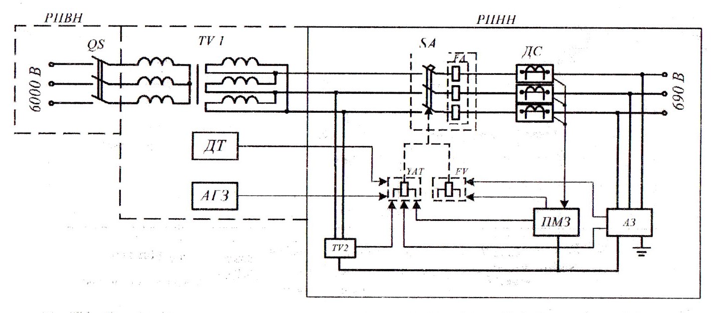
Figure 6.2 - Typical layout of a package transformer substation
Dry explosion-proof transformers of series 2TCV and TSV are used for power supply to consumers working in underground mines of hazardous gas or dust. The transformer consists of an active part, placed in a casing with a traveling trolley. The upper and lower voltage input boxes are placed from the end faces of the casing. The transformer casing, depending on the power, has a round, oval or pear-shaped cross-section, finned or corrugated surface. The high voltage winding has bends for adjusting the voltage by ± 5% relative to the rated voltage. Access to the control tap-off panel is via hatch 5, in accordance with Figure 6.3, a) located on the side wall of the casing. The input devices of low voltage of transformers with the power of 100 ... 400 kVA allow the winding connection according to the star or triangle scheme.
If it is necessary to implement a separate power supply for consumers in the underground power supply system, a separating transformer TSVR-630 / 6-6 is used. In order to compensate for the voltage losses in the transformer, the transformation ratio is assumed equal to 0.96 in the rated load mode. Therefore, the secondary winding has a voltage x.x. 6270 V. For connection of the high-voltage protection device against leakage current, the secondary winding is connected to a star with a deduced zero point.
For power supply of underground consumers with voltages of 380 V, 660 V and 1140 V, complete transformer substations of the series TSVP and KTPV are widely used. The use of complete transformer substations makes it possible to approximate the voltage of 6 kV as close as possible to consumers, to provide high mobility of movement, to facilitate the installation and movement of electrical equipment. The complete transformer substation consists of the following main components, in accordance with Figure 6.3: transformer 3, high voltage switchgear 2, low voltage switchgear 4 and chassis 1. As part of the complete transformer substation, 2TB transformers of the appropriate capacities are used. In the construction of substations, internal unloading devices (URG-1; URG-2) were used. They function as a valve, and in the event of a methane-air mixture explosion in one of the transformer substation compartments, the explosion products (at their excess pressure) are opened to the adjacent compartment (while cooling the explosion products to a safe temperature). This allowed to reduce the estimated overpressure and reduce the thickness of the shells of the complete transformer substation. To drain the condensate in the lower part of the casing, there are explosion-proof plugs filled with crushed quartzite or glass beads.
The high-voltage switchgear is housed in an explosion-proof enclosure that is attached to the transformer casing by means of a flange connection. In the upper part of the high voltage switchgear there is an opening box, and in the end part - a hinged cover. The shell has a built-in three-pole disconnector - a load switch (QS) with a manual drive, which is able to disconnect the current of the loaded transformer. Its handle 2 is located on the side wall of the sheath of the high voltage switchgear, in accordance with Figure 6.4. To monitor the visible rupture of the disconnector contacts in the enclosure, there are inspection windows 1. In order to prevent rapid wear of the contact groups of the disconnector, a lock is installed preventing it from being used to disconnect the complete transformer substation under load. This interlock is provided between the disconnector of the high voltage switchgear and the circuit breaker by a low voltage switchgear. It provides preliminary disconnection of the circuit-breaker of the low-voltage switchgear with the corresponding button, the pusher 5, shown in Figure 6.4, which is exposed to the outer side of the sheath of the high-voltage switchboard near the handle of the 2 disconnector. Only when the pusher is pushed it is possible to turn this handle and disconnect the power circuit of the complete transformer substation from the input side of its transformer.
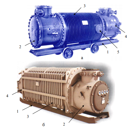
Figure 6.3 - Complete transformer substations of the mine site: TSVP (a); KTPV (b)
Figure 6.4 shows the following fragments of the enclosure of the high voltage switchgear of the complete transformer substation:
- sight glass
- disconnector handle
- pusher of the switch button of the circuit breaker of the low voltage switchboard
Conclusions and Objectives
The electrotechnical complex consists of the following components:
- Complex transformer substation. They are used to convert an AC voltage of one level into an alternating current voltage of another level of the same frequency. Two-winding transformers with a primary voltage of 35-115 kV and a secondary 6.3-6.6 kV are used to supply the mines with natural oil cooling or with blowing and natural circulation of oil.
- Circuit breaker. It provides instant switching on and off of the device at a speed that does not depend on the operator, kind and mass of the drive; It excludes the possibility of holding the contacts of the device in the on position when the protections are activated.
- Starters and control stations. They are designed for remote connection, disconnection and reversal of asynchronous motors of technological machines and installations of the mine site.
- Cables
Thus, the technical means of the district electrotechnical complexes of the mine are a combination of the creation, power switching, distribution and consumption of electricity.
Probable emergency and dangerous conditions of the mine district power grid should be considered:
- interfacial short circuits;
- interphase arc formation;
- the formation of a circle of increased conductivity between phase and earth as a result of the contact of the phase conductor by a man (circles of sources of current to earth);
- current overloading of electrical equipment;
- incompletely phase power supply of induction motors.
The emergence of these states should cause the automatic protective high-speed to de-energize the network.
The aim of the work is to increase the efficiency of operation of the district electrotechnical complex of the mine due to the justification and development of a maximum overcurrent protection of increased speed.
To achieve this goal, it is necessary to solve the following tasks:
- critical review of existing technical solutions
- development and study of the mathematical model of the electrotechnical complex of the mine site in the state of interphase short-circuit with the purpose of justifying the principle of detecting this regime at the initial stage of its existence;
- technical implementation of overcurrent protection [1]
List of sources
- Automatic protection of electrical equipment of mines from emergency conditions and hazards: a textbook for higher education institutions / KN Marenich, I.V. Kovalev. - Donetsk: DVNZ DonNTU, 2013. - 209 with.
- Dzyuban V.S. Devices for protection against leakage currents in mine electric networks / В.С. Dzuban. - Moscow: Nedra, 1982. - 152 p.
- Dzyuban V.S. Explosion-proof low voltage devices / В.С. Dzuban. - Moscow: Energoatomizdat, 1993. - 240
- Bariev N.A. Protective earthing of mine electrical equipment / N.A. Bariev. - Moscow: Nedra, 1965. - 76 p.