Annotation
Kremlevsky P.P. Ultrasonic flowmeters In this paper, we consider varieties of ultrasonic flowmeters and the operating principle of the species presented.
Ultrasonic flowmeters
Ultrasonic flowmeters are devices based on the measurement of a flow-dependent effect that occurs when acoustic vibrations pass through a fluid or gas stream. Almost all practiced acoustic flowmeters operate in the ultrasonic frequency range and are therefore called ultrasonic.
The ultrasonic flowmeter is a device whose direct purpose is to measure the acoustic effects produced by the movement of a substance whose flow is to be measured. The decision to buy an ultrasonic flowmeter will be ideal if you want to measure the volume or flow of any liquids transmitted by a pressure line. If strict monitoring and recording of such parameters as the flow of cold or hot water, the volume of supply of various oil products, gas or waste are necessary, the best option is to order ultrasonic flowmeters that will help to quickly and easily monitor these parameters.
The management of most modern enterprises is of the opinion that the price of a flowmeter is an unimportant measure when it comes to saving on the scale of a corporation. A modern ultrasonic flowmeter is a device that is characterized by its simplicity and reliability in operation, as well as high accuracy, which makes it an excellent solution for a low price.
They are divided into flowmeters based on the movement of acoustic vibrations by the moving medium, and flowmeters based on the Doppler effect, which appeared later. The main distribution is flowmeters, based on measuring the difference in the times of passage of acoustic oscillations along and against the flow. Significantly less often there are ultrasonic flowmeters in which acoustic vibrations are directed perpendicular to the flow and the degree of deviation of these oscillations from the original direction is measured. Ultrasonic flowmeters based on the Doppler phenomenon are intended primarily for measuring local velocity, but they also find application for measuring flow. Measuring circuits for them are simpler.
Along with these three types of ultrasonic flowmeters, there are acoustic flowmeters, called long-wave meters, operating in the acoustic frequency range of acoustic oscillations.
Ultrasonic flowmeters usually serve to measure volumetric flow, because the effects that occur when acoustic vibrations pass through a fluid or gas flow are related to the speed of the latter. But by adding an acoustic transducer that reacts to the density of the measured substance, it is also possible to measure the mass flow. The resulted error of ultrasonic flowmeters lies in wide limits from 0,1 to 2,5%, but on the average can be estimated by figures 0,5-1%. Much more often ultrasonic flowmeters are used to measure the flow rate of a liquid, rather than a gas, due to the small acoustic impedance of the latter and the difficulty of obtaining intense sound vibrations therein. Ultrasonic flowmeters are suitable for pipes of any diameter, starting from 10 mm or more.
Existing ultrasonic flowmeters are very diverse both in the arrangement of the primary converters and in the measuring schemes used. When measuring the flow rate of pure liquids, high frequencies (0.1-10 MHz) of acoustic vibrations are usually used. When measuring polluted substances, the oscillation frequencies must be significantly reduced up to several tens of kilohertz in order to avoid the scattering and absorption of acoustic oscillations. It is necessary that the wavelength is an order of magnitude greater than the diameter of solid particles or air bubbles. Low frequencies are used in ultrasonic gas flow meters.
Emitters and receivers of acoustic oscillations.
To introduce acoustic oscillations into the flow and to receive them at the output from the stream, radiators and oscillation receivers are needed - the main elements of the primary transducers of ultrasonic flowmeters. When the compression and tension in certain directions certain crystals (piezoelectric elements) on their surfaces electric charges are formed, and conversely, if these surfaces to apply an electric potential difference, the piezo stretch or shrink depending on, there will be more stress on any of the surfaces - reverse piezoelectric effect. The latter is based on the work of radiators that convert an alternating electrical voltage into acoustic (mechanical) oscillations of the same frequency. On the direct piezoelectric effect, receivers that convert acoustic vibrations to alternating electrical voltages operate.
The piezoelectric effect was first observed in natural quartz. But now only ultrasonic flowmeters use almost everywhere only piezoceramic materials, mainly barium titanate and lead titanate zirconate-a solid solution of zirconate and titanate, lead, which have a large piezomodule and a high dielectric constant, than in quartz. After special treatment of the surface of the radiators and receivers, they are covered with a layer of metal (in most cases by silvering). The connecting wires are soldered to this layer
To obtain intense acoustic oscillations it is necessary to work at the resonant frequency of the piezoelectric element. For pure liquids, it is advisable to operate at high resonant frequencies and therefore thin piezoceramic plates should be used. For substances containing mechanical impurities or gas bubbles, when a small frequency is necessary, it is necessary to apply piezoceramics of large thickness or on two sides of a thin piezoceramic plate to glue thick metal plates. Emitters and receivers in most cases are made in the form of round disks with a diameter of 10-20 mm, sometimes less.
The principle of operation and varieties of ultrasonic flowmeters with oscillations directed along and against the flow.
In most cases, the planes of the emitting and receiving piezoelements are located at some angle to the axis of the tube. Passage of ultrasound directed along and against the stream is characterized by the value of the speed of passage of the required distance and the time spent on its passage.
Thus, the time difference is directly proportional to the speed.
There are several ways to measure a very small time value: phase, in which the difference in phase shifts of acoustic oscillations directed along and against the flow (phase flowmeters) is measured; time pulse method based on direct measurement of the difference in the time of passage of short pulses along and against the flow (time-impulse flowmeters); frequency method, in which the difference between the repetition frequencies of short pulses or acoustic wave packets directed along and against the flow (frequency flowmeters) is measured. The last method and its variants became widely used.
According to the number of acoustic channels, ultrasonic flowmeters are divided into single-beam or single-channel, two-beam or two-channel and multi-beam or multi-channel. The former have only two piezoelements, each of which in turn performs the functions of radiation and reception. Their significant advantage is the lack of spatial asymmetry of acoustic channels, which depend on the difference in their geometric dimensions, as well as the differences in temperature and flux concentration in them. The latter have two radiators and two receivers, forming two independent acoustic channels, which are arranged in parallel or crossed with each other. Multichannel is used when measuring the flow rate of deformed flows or for achieving higher accuracy, in particular, when using an ultrasonic flowmeter as an exemplary one.
Influence of the velocity profile.
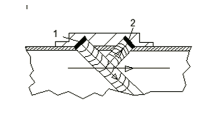
The velocity profile has a significant effect on the ultrasonic flow meter readings and their error. Consider this effect for the most common flowmeters with an angular introduction of acoustic oscillations at one point. In this case, the ultrasonic beam will respond to a velocity averaged over the diameter, which will always be greater than the average velocity averaged over the cross-sectional area of the pipeline. If acoustic vibrations are not sent in the diametric plane, but in a plane passing through any of the chords. Indeed, as the chord moves away from the diameter, the velocity averaged over the chord will decrease and at a certain distance between the diameter and the chord equal to (0.5-0.54) D / 2, the velocity in the turbulent zone becomes equal to the average velocity. Probing over the chord improves the accuracy of flow measurement, especially if it is performed over several chords, but the ultrasonic flow meter device becomes more complicated. Probing for several chords is advisable, first of all, in the model installations, as well as in the measurement of deformed flows, especially in pipes of larger diameter, where it is difficult to provide a sufficient length of the straight section. This gives a reduction in error of up to 0.1%, but here, with a laminar regime, the error increases to 3.5%. Greater accuracy is obtained by probing four (Fig. 1, b, c) or five chords. There are several variants of the arrangement of the four chords. In one of them two parallel chords are located at a distance of 0.5D / 2 from the horizontal diameter, and two parallel others at the same distance from the vertical diameter (Figure 1, b). Here, the lengths of all chords are equal, which simplifies the processing of measurement results. In another variant (Fig.1, c), all four chords are parallel, two of them being at a distance of 0.309D / 2, and the other two at a distance of 0.809D> / 2 from the diameter.
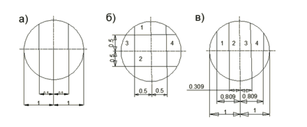
Figure 1. Schemes of location of chords for acoustic sounding in an ultrasonic flowmeter.
Probing on the five chords can be carried out in different ways. Sounding on five parallel chords, the location of which is chosen according to the Gauss quadrature formula.
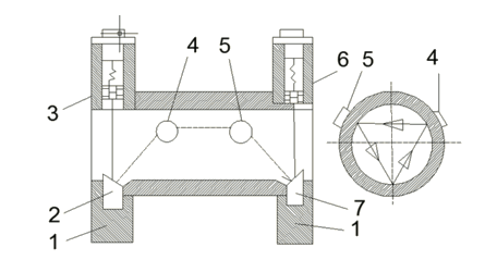
Figure 2. Ultrasonic flowmeter with acoustic sounding for three spatial chords.
Probing can be carried out in succession along five chords, located at a distance of 0.5D / 2 from the center of the tube and located not in one plane, but in space (Figure 2). In flanges 1 and 8 two piezoelements 3 and 6 and two reflectors 2 and 7 are mounted. The other two reflectors 4 and 5 are on opposite sides of the pipe wall. The piezoelectric element 3 is recessed to reduce the effect of acoustic interference. The projection of the chords through which the acoustic channels pass is crossed perpendicular to the axis of the pipe, forming an equilateral triangle. With sequential sounding, the signal processing circuit is simplified and reverberation interference is eliminated, since the working and reflected signals are separated in time. Multichannel acoustic flowmeters can provide high accuracy, do not require experimental calibration and can be used as exemplary, but they are complex and relatively rare.
For conventional ultrasonic flowmeters with sounding in the diametric plane, either an experimental calibration or a determination of the correction factor with sufficient accuracy is necessary. Unfortunately, it's not so easy to accomplish this. In fact, the oscillations propagate in a narrow space bounded by planes passing through two chords, each of which is separated from the diametric plane at a distance d / 2 in either direction (d is the diameter of the radiating piezoelectric element). In addition, due to the difference in speed across the cross-section of the tube, the path of the ultrasonic beam differs from the rectilinear one.
To improve the accuracy of the ultrasonic flowmeter, a nozzle or converging cone (confuser) can be installed in front of the flow transducer, creating a very uniform velocity profile at the output, at which the factor can be taken equal to unity. This is especially necessary when the length of the straight section is insufficient and, consequently, the deformed velocity profile. If there are resistors in the pipeline, twisting the flow, then a jet of a rectifier should be placed in front of the nozzle or confuser.
With small pipe diameters, the hydrodynamic error can be eliminated if a flow transducer with a rectangular channel and rectangular piezoelements are produced creating acoustic oscillations along the entire flow cross-section.
Transducers of ultrasonic flowmeters.
The ultrasonic flowmeter transducer consists of a piece of pipe, on which two or four piezoelements are mounted. With a few exceptions, discs that direct radiation are used. If the piezoelements are installed outside the tube, then the refraction of the beam occurs in its walls, but even when the piezoelectric elements are installed internally, it is sometimes considered advisable to fill the inner cavity of the corner pockets with sound ducts made of metal or organic glass, in which the beam also refracts. Take into account the demolition only in converters having a refraction of the beam, and the influence of the flow velocity can be neglected.
Usually the diameter of the piezoelements is in the range of 5-20 mm. and their thickness as a function of frequency. In frequency and time-impulse flowmeters, a high frequency of 5-10 MHz, and sometimes even 20 MHz, is chosen because the increase contributes to the improvement of measurement accuracy. In phase flowmeters, the frequency is chosen so that at the maximum flow rate, the largest phase difference is obtained, which can be measured by a phase meter. Usually the frequency is from 50 kHz to 2 MHz. This applies to liquids. In gas media, it is necessary to reduce the frequency to hundreds and tens of kilohertz because of the difficulty of creating intense acoustic vibrations in gases, especially high frequency.
With small pipe diameters, sometimes circular discs and receivers are used instead of discs. In Fig. 3 shows the basic schemes of ultrasonic flowmeter transducers. In the first two schemes (Fig. 3, a, b), annular piezo transducers are used, creating non-directed, and spherical radiation. The first of these circuits (a) is single-channel, in which each of the two piezoelements alternately radiates and receives acoustic vibrations. The second circuit (b) is a two-channel, medium piezoelement - radiating, and two extreme ones - receiving.
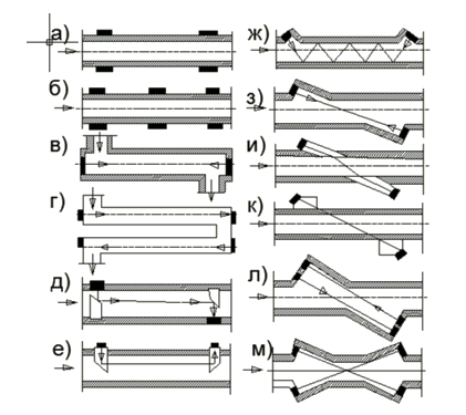
Figure 3. Schemes of transducers of ultrasonic flowmeters.
Converters of spherical radiation are used only in pipes of very small diameter in order to obtain a sufficient length of the measuring section, which would be very small for angular directional radiation input at small values of the diameter. A larger length can also be obtained with disk converters if the radiation is directed along the axis of the tube (Figure 3, c, d), if there is multiple reflection of the wave from the pipe wall (Figure 3, g), if reflectors are used (Figure 3, d ) or special waveguides (Figure 3, e). The latter are particularly useful when it is necessary to protect the piezo transducer from an aggressive medium. The circuit of Fig. 3, d - two-channel, the rest - single-channel. Significantly more often, schemes with angular introduction of directed acoustic oscillations are used. In Fig. 3, x-k show single-channel, and in Fig. 3, l, m - two-channel circuits. In most cases (Fig. 3. ж-и, л, м) pipelines are supplied with special depressions - pockets, in the depth of which piezoelements are placed. Cavities of pockets can be free (Fig. 3, f, s, l, m) or filled with a sound pipe made of metal or organic glass (Fig. 3, i). In some cases (Fig. 3, k) piezoelements are located outside the pipeline. They transmit acoustic vibrations through the metal, and sometimes liquid, sound pipe of the pipe wall and further to the substance being measured. The transducers according to the schemes in Fig. 3, and, k work with the refraction of the sound beam. A special scheme of a converter with multiple reflections is shown in Fig. 3, f. To increase the path, the sound beam moves in a zigzag pattern, reflected from the opposite walls of the channel. Such a converter has been studied when operating in small channels of square and circular cross sections.
Converters with free pockets to avoid their clogging are used only for clean and non-corrosive environments. Nevertheless, some firms provide for the supply of water for cleaning. Another of their drawbacks is the possibility of vortex formation and the influence on the velocity profile.
Converters with refraction (Fig. 3, i, k) are devoid of these drawbacks. In addition, they contribute to reducing the reverberation error, since they prevent the reflected element from reaching the receiving element. But when the temperature, pressure and composition of the measured substance change, the angle of refraction and the speed of sound in the material of the sound line will change. An important advantage of converters with external piezoelements (Fig. 3, k) is the absence of contact with the measured substance and the non-violation of the integrity of the pipeline. However, there is an increased level of parasitic signals and interference caused by the passage of acoustic vibrations along the pipe wall, and its sensitivity is much worse.
An example of a simple design of a piezo element assembly of a gasoline flow converter is shown in Fig. 4.
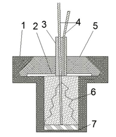
Figure 4. Transducer flowmeter.
Inside the tube 3 fixed on the grid 2, conductors 4 pass, one of which is connected to the center of the disk piezoelectric element 7, and the other, by means of the contacts 6 of the foil, with its edges. All this is filled with epoxy compound 5 and protected by fluoroplastic sheath 1. Long-term plant operation confirmed the reliability of this unit.
More complicated is the arrangement of the converter assembly with a liquid sound pipe located outside the pipeline. Such a converter is designed for pipes having a diameter of 150 mm and serves to measure liquid flow rates within the range of 20-200 m3 / h at a pressure of 0.6 MPa, it is used in flow meters for small pipes.
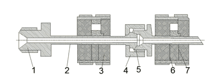
Figure 5. Converter with ring piezoelements for pipes of small diameter.
Inside the insulating sleeve there is a disk piezoelectric cell with a diameter of 20 mm. He presses against the membrane of Plexiglas. Further acoustic vibrations are transmitted through the compressor oil and the pipeline wall to the substance being measured. The oil is poured into the cavity formed by the body and the platform, polished in the wall of the pipeline.
An example of the use of ring-shaped piezoelements for pipes of small (less than 10 mm) diameter (corresponding to the scheme in Fig. 3, b) is shown in Fig. 5. It shows only two parts of the measuring section of the pipeline 2, connected by nakidnymi nuts 4 and equipped with fittings 1. The ring piezoelements 7, to which the voltage is fed through the contact rings 6, are glued to the pipe with epoxy resin. On both sides of each piezoelement, the pipe is covered with epoxy resin with filler 3. This helps to weaken the parasitic acoustic oscillations running along the pipe wall. The fluoroplastic gaskets 6 and sharp changes in the cross-sections of the wall at the junctions serve the same purpose. The design is designed for pressure up to 50 MPa.
Phase ultrasonic flowmeters.
Phase ultrasonic flowmeters, based on the dependence of the phase shifts of ultrasonic oscillations arising on the receiving piezoelements, on the difference in the times of passage through these oscillations of the same distance along the flow of a moving fluid or gas and against it, are called phase meters. Indeed, provided that the initial phases of both oscillations having a period and frequency are exactly the same. Many circuits of single- and dual-channel phase flowmeters were proposed and implemented. In single-channel flowmeters, the switching schemes of piezoelements from radiation to reception differ in great variety, in particular, schemes with simultaneous sending of short ultrasonic packages and simultaneous switching of piezoelements from radiation to reception. A similar circuit was used in a single-channel flowmeter designed to measure the flow rate of a polyethylene slurry in gasoline in a pipe 150 mm in diameter, Q = 180 m / h, and a 1 MHz oscillation frequency. The radiation angle is 22 °. The error is ± 2%. The piezoelements are located outside the pipe (see Figure 3, k). The electronic circuit of the flowmeter includes a switching device; master oscillator; two oscillators of amplitude-modulated oscillations arriving at piezoelements; a phase adjustment device consisting of a limiter amplifier, a power amplifier, a reversing motor, a phase shifter and a phase splitter; a measuring phase meter and synchronization clock, each of which consists of a cathode follower, selector amplifiers, a phase detector and an automatic gain control circuit.
In a flowmeter designed to control oil and petroleum products, the switching of piezoelectric elements from radiation to reception is performed using a multivibrator controlling the modulators of the master oscillator. A special generator generates a sinusoidal low-frequency voltage, from which rectangular pulses are formed in the trigger device. The trailing edge of these pulses serves to activate the multivibrator.
In the flowmeter circuit, ultrasonic oscillations with a frequency of 2.1 MHz for 500 ?s propagate towards each other with a phase shift of 180 °, after which the multivibrator switches the piezoelectric elements from the radiation mode to the reception mode. In another foreign flowmeter, switching is performed by a special generator that generates signals of two forms. One of the signals includes a generator that vibrates the piezoelectric elements, the second signal switches the piezoelectric elements to reception. The received oscillations after amplification are converted into pulses of a rectangular shape. After passing through the phase shift detector, the width of the pulses at the output is proportional to this shift. At the output after rectification, we have a DC voltage proportional to the flow rate. The oscillation frequency is 4.2 MHz, the switching frequency of the piezoelectric elements is 4.35 kHz. The angle of inclination of piezoelements is 300. The diameter of the pipe is 100 mm.
Due to the complexity of most piezoelectric switching circuits, one-channel phase meters that do not require switching are created from radiation to reception. In such flowmeters, both piezoelements continuously emit ultrasonic vibrations of two different but very close frequencies, for example, 6 MHz and 6.01 MHz.
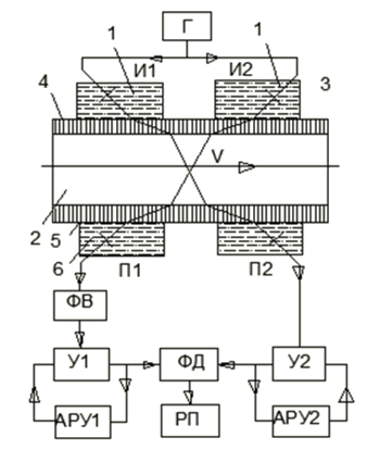
Figure 6. Scheme of the phase ultrasonic flowmeter.
More simple electronic circuits have two-channel phase flow meters. In Fig. 6 is a schematic diagram of a flow measurement fluid in pipes having D of 100 and 200 mm and calculated for Qmax of 30; 50; 100; 200 and 300 m3 / h. Frequency 1 MHz, the maximum phase difference (2-2,1) rad. The error of the flowmeter is +2.5%. The generator Г was connected with the matching piezoelements Il and I2 by means of matching transformers. The ultrasonic vibrations emitted by the latter pass through the liquid waveguides 1, the membranes 3 sealed in the walls of the pipeline 4 pass through the measured liquid 2 and then through the membranes 5 and the liquid waveguides 6 enter the receiving piezoelectric elements P1 and P2. The latter at the output are connected to the phase-by-phase circuit in the phase-regulator FV; two identical amplifiers V1 and V2, controlled by automatic adjustment nodes AGC1 and AGC2; phase detector PD and a measuring device (potentiometer) RP. The phase regulator PV is intended for adjustment of the initial point of the phase detector and zero correction. The resulted error of the flowmeter is ± 2,5%. Phase flowmeters were formerly the most common among ultrasonic, but at present, other flowmeters with which a higher measurement accuracy can be used are preferred.
Frequency ultrasonic flowmeters.
Frequency is called ultrasonic flowmeters based on the dependence of the difference in repetition frequency of short pulses or ultrasonic vibration packages on the difference in the times of passage through these oscillations of the same distance along the flow of a moving fluid or gas and against it.
Depending on whether the frequency differences of the packages of ultrasonic vibrations or short pulses passing through a liquid or gas are measured, the flowmeters are called frequency-packet or frequency-pulse. A schematic diagram of the latter with two acoustic channels is shown in Fig. 7. The generator D creates high frequency oscillations (10 MHz), which, after passing through the modulators M1 and M2, enter the piezoelectric elements Il and I2. As soon as the first electrical oscillations produced by the piezoelements P1 and P2, passing through the amplifiers V1 and V2 and the detectors D1 and D2, reach the modulators M1 and M2, the last ones operating in the trigger mode lock the oscillation passage from the generator F to the piezoelectric elements U1 and U2. Modulators open again when the last oscillations reach them. The device connected to the mixing stage Cm will measure the frequency difference.
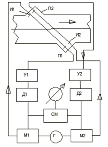
Figure 7. Frequency-batch two-channel flowmeter.
In frequency-pulse flowmeters, the generator generates non-continuous oscillations, and short pulses. The latter arrive at the radiating piezoelements at intervals equal to the time of passage of ultrasound along and against the flow velocity. They have frequencies twice as large as those of frequency-packet flowmeters. A small frequency difference in frequency flow meters is a significant drawback that makes it difficult to accurately measure.
Therefore, several ways of increasing the frequency difference realized in frequency meters, constructed in most cases by a single-channel scheme, are proposed. Among these methods is the separation from the harmonic frequencies and the measurement of the difference frequency, as well as the multiplication of the difference k times before entering the measuring device. The methods for multiplying the difference frequency can be different.
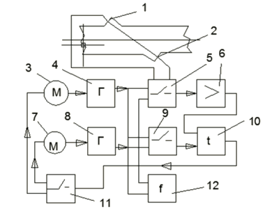
Figure 8. Scheme of single-channel frequency flowmeter.
In Fig. 8 shows the scheme in which the frequency difference between two controlled generators is measured, the periods of which, by means of automatic frequency tuning, are set in k times shorter than the propagation time of ultrasonic oscillations in the direction of the flow velocity and against it. The single-channel flow transducer has piezoelectric cells 1 and 2, to which pulses are alternately supplied: to the first from the generator 4 with a repetition period T1, and to the second from the generator 8 with a repetition period T2. The time of passage of acoustic impulses in the pipeline along and along the flow m1, m2, is k times longer than the periods T1, and T2, respectively. Therefore, in the flow simultaneously it will be to the impulses. When sending acoustic pulses through the flow, the switch 5 simultaneously connects the piezoelectric cell 1 to the generator 4, to the piezoelectric element 2 to the amplifier of the receiving signals 6. When the pulses are sent back, the generator 8 is connected to the piezoelectric element 2 and the amplifier 6 to the piezoelectric element 1. From the output of the amplifier 6, the input of the time discriminator 10, which simultaneously through the commutator 9 receives pulses from the generator 4 or 8, creating a reference voltage on the discriminator. The voltage at the output of the discriminator is zero if the pulses from the amplifier 6 arrive simultaneously with the pulses from the generators. Otherwise, a voltage will appear at the output of the discriminator, the polarity of which depends on whether or not they are ahead of the reference pulses from the amplifier 6. This voltage is transmitted through the commutator 11 through amplifiers to the reversing motors 3 or 7, which change the oscillation frequency of the generators 4 and 8 to As long as the voltage at the output of the discriminator becomes zero. The difference in the frequencies of the pulses produced by the generators 4 and 8 is measured by the frequency counter 12. The flowmeters analogous to the considered are sometimes called frequency-time.
Another way to multiply the difference frequency is to measure the difference in frequencies between two high frequency generators, of which one oscillation period is proportional to the transit time of the acoustic oscillations in the direction of flow, while the other is proportional to the time of passage of the acoustic oscillations against the flow. After passing through the dividing device, two pulses are sent every 6 ms, separated by time. The first pulse passes through the flow (or against it) and after amplification it enters the comparison circuit, where the second pulse is also fed without a passage, through the acoustic path. If these two pulses are not received at the same time, then the device regulating the frequency of one generator is switched on until both pulses are simultaneously applied to the comparison circuit. And this will happen when the period of these impulses is equal. Accuracy of flow measurement does not exceed ± 1%.
In the single-channel frequency-pulse flowmeters considered, there is alternate switching of pulses directed along and against the flow. This requires accurate measurement and memorization of the frequencies of the auto-circulation of pulses along and against the flow with the subsequent measurement of the difference. In addition, non-simultaneous sensing along and against the flow can give an error due to a change in the hydrodynamic properties of the flow. These drawbacks are deprived of single-channel flowmeters in which both ultrasonic signals are simultaneously auto-circulated along and against the flow, which are completely inertial.
This eliminates the large errors inherent in the ways of memorizing the frequencies of the auto-circulation of ultrasonic signals along and with the flow, followed by the separation of the signal of the frequency difference of the autocirculation, the separation of the difference frequency signal based on the tuning of the generator frequencies, on the reverse pulse count, etc. In addition, automatic renewal of their action when the circuit is broken due to the appearance of acoustic opacity of the substance in the pipe (the appearance of the gas phase, full or partial fluid withdrawal), the flowmeters indicate the direction of the flow and measure the flow in both directions of the flow. The flowmeter showed its good operability in a long factory operation, the resulted error of the flowmeter does not exceed ± 0.5%. The flowmeter is designed for dynamic measurement of fuel consumption in aircraft engines, as well as for measuring fuel in trucks. The results of the tests showed that the measurements by the flowmeter did not change when the flow was sharply rotated at an angle of 90 ° at a distance of one diameter of the conditional pass before the transducer in the plane of the axis of the transducer and the axis of the piezoelement assemblies, ie, the lengths of the straight sections of the pipes are not required at all. The transitional region of the flow in the converter was in the initial section of the calibration characteristic of the flowmeter. There was no sharp inflection or fracture of the characteristic in the initial section, the initial section of the calibration characteristic was the same. The instrument has a very high convergence measurement. At different points of the measuring range with steady flow, all four digits of the results were repeated.
Time-pulse ultrasonic flowmeters.
Time-pulsed is called ultrasonic flowmeters, in which the difference in the times of displacement of short pulses along and along the flow direction is measured.
Time-pulse flowmeters are in most cases single-channel and operate on very short pulses of duration 0.1-0.2 microseconds sent to meet one another alternately or simultaneously with a frequency, for example, 0.5 kHz.
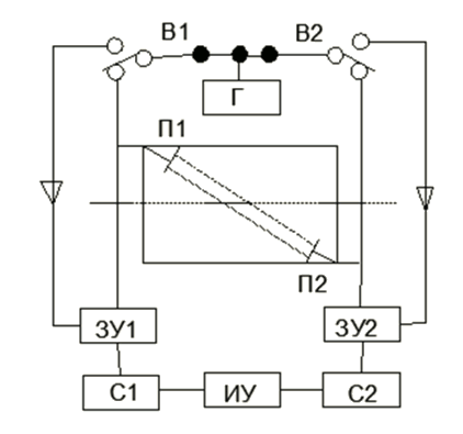
Figure 9. The scheme of a single-channel time-impulse flowmeter.
In Fig. 9 shows a simplified diagram of one time-pulse flowmeter. The generator D generates pulses having an amplitude of 700 V, a duration of 0.2 ?s and a repetition frequency of 800 Hz, which are fed alternately to the piezoelectric elements P1 and P2 by means of vibrators B1 and B2 operating at a frequency of 400 Hz. The latter send rapidly damped ultrasonic pulses into the liquid, and the vibrators B1 and B2 include the chargers ZU1 or ZY2. The generator P simultaneously receives a pulse to the piezoelectric element PI and an impulse to the flip-flop 3Y2. setting it into an active state of conductivity. At the same time, the device C2 is activated, which generates a sawtooth voltage for the time, the passage of ultrasound through the substance to be measured. The maximum value of this voltage is proportional to the time. When the ultrasonic pulse arrives at the piezoelectric element P2, the device C2 is switched off. In the same way, during the passage of the ultrasonic pulse against the flow from P2 to P1, the device C1 generates a voltage proportional to the time. The voltage difference is measured by the IW device. This cycle is repeated 400 times per second. The total error of the flow measurement is ± 0.5%.
In one domestic time-pulse flowmeter, in order to increase the dynamic characteristics and eliminate the possibility of the appearance of an error from asymmetry, short pulses are simultaneously applied to both piezoelements, exciting ultrasonic vibrations moving towards each other. After reaching the opposite piezoelectric elements in the latter, electrical pulses are formed which, together with the pulses from the generator, pass through amplifiers and drivers, and then they enter the device producing a voltage proportional to the time.
Ultrasonic flowmeters with correction to the speed of sound and the density of the measured substance.
The ultrasonic flowmeters considered earlier serve to measure volumetric flow. To measure mass flow, it is necessary to have a separate additional piezoelectric element, excited at a resonant frequency, which sends acoustic vibrations to the substance being measured. The voltage taken from it is proportional to the specific acoustic resistance of the substance, if the latter is much less than the resistance of the generator. Multiplying the electrical signal generated by this piezoelectric cell by a signal proportional to the volume flow, we obtain a signal proportional to the mass flow at the output. A similar device used in a flowmeter with acoustic oscillations perpendicular to the flow is shown in Fig. 13.
To eliminate the error from the change in the ultrasound velocity c, special correction schemes are applied in phase and time-pulse flowmeters in the measured substance. For this purpose, an additional pair of piezoelements is installed at opposite ends of the pipeline diameter. The time of passage of acoustic oscillations between them is inversely proportional to the velocity. The corresponding corrective measuring signal is proportional to the speed. It is squared and the main signal of the flowmeter is divided into it. Obviously, the resulting signal will be proportional to the speed and will not depend on the speed of ultrasound. Figure 10 shows a diagram of such a single-channel phase flow meter. The software device PU provides alternate supply from the generator G of electrical oscillations with a frequency of 1/3 MHz and to the piezoelectric elements P1 and P2 via the commutator K. The received oscillations from these piezoelements come through the switch K, the receiver device P and the frequency converter V2, which reduces the frequency to 1/3 kHz, to the IF phase difference meter between them and the initial oscillations coming from the generator Г through the frequency converter 11. Device I measures the phase difference difference proportional to the time difference, the passage of ultrasound through and against the flow, and generates a signal proportional to the speed.
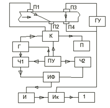
Figure 10. Schematic diagram of single-channel phase flow meter with correction to sound velocity.
Piezoelectric cells PZ and P4 have their own generator-amplifier GI and produce a signal proportional to the transit time of ultrasound between them and, consequently, proportional to the speed of sound. In the IK device, the signal divides into a square of the signal and a signal proportional to the velocity is received in the measuring device of the PI. Its relative error is 1%. There are schemes with compensation for the influence of ultrasound velocity for time-impulse flowmeters.
The readings of the frequency flowmeters are independent of the speed of sound and therefore no correction for the ultrasound velocity is required here. But if the frequency flow meter measures the mass flow, then a piezoelectric cell operating at the resonant frequency is needed. With its help, a signal proportional to the resistance of the substance is formed, from which the speed multiplier must be eliminated. For this purpose, a block is added to the circuit to add the frequencies of repetition of pulses or acoustic wave packets along and against the stream, bearing in mind that the sum of the frequencies is proportional to the speed. The circuit of such a frequency-flow meter is shown in Fig. 11.
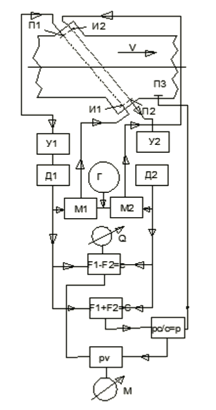
Figure 11. Scheme of the frequency-packet mass flowmeter.
Ultrasonic flowmeters with oscillations perpendicular to movement.
These ultrasonic flowmeters are significantly different from those previously considered that there are no acoustic oscillations directed along and against the flow. Instead, the ultrasonic beam is directed perpendicular to the flow of the flow and the degree of deflection of the beam from the perpendicular direction is measured, depending on the velocity and the substance being measured. Only one piezoelectric element radiates acoustic vibrations. These oscillations are perceived by one or two piezoelements.
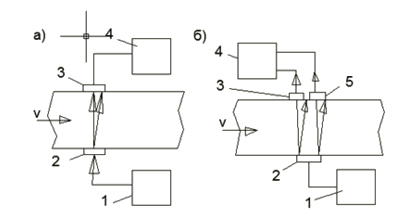
Figure 12. Diagram of a flowmeter with radiation perpendicular to the axis of the tube: a) - with one receiving piezoelectric element, b) - with two receiving piezoelements; (1-generator, 2-radiating piezoelement, 3, 5-receiving piezoelements, 4-amplifier)
With one receiving element (Fig. 12a), the amount of acoustic energy supplied to it will decrease with increasing speed, and the output signal of the amplifier will fall. One work indicates that the signal becomes zero at a speed of = 15 m / s (piezoelement diameter 20 mm, frequency 10 MHz). With two receiving piezoelectric elements 3 and 5 (Fig. 12b), located symmetrically with respect to the emitter 2, the output signal of the differential amplifier 4 increases with increasing speed. At a speed of = 0, the output signal is zero here due to the equality of the acoustic energy arriving at the piezoelectric elements 3 and 5. Switched towards each other. The flowmeters under consideration are simple in design. The scheme with differential inclusion of piezoelements is better. It improves the stability of the readings, which is disturbed in the circuit with one receiving piezoelectric element. change in the absorption coefficient under the influence of random causes. Nevertheless, the accuracy of flow measurement is limited by the low sensitivity of the method itself.
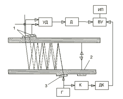
Figure 13. Schematic of a flowmeter with multiple reflections.
In this connection, flowmeters with numerous reflections of acoustic vibrations from the pipe walls are proposed. The oscillations are directed not perpendicular to the axis of the tube, but form a small angle with it (Figure 13). The path of the ultrasonic beam at speed = 0 is shown by a solid line. In this case, both the receiving piezoelectric elements receive the same amount of acoustic energy, and there is no signal at the output of the differential amplifier. The path of the ray when the velocity v appears appears as a dashed line. The higher the speed, the greater the amount of energy the left receiver piezoelectric cell receives compared to the right one, and the greater the signal will be at the amplifier output. The signals from the generator G are fed to the emitter 3 and the commutator K. The auxiliary piezoelectric element, excited at the resonant frequency, gives a signal proportional to the acoustic resistance of the substance being measured. This signal through the circuit and the correction detector DK enters the computer unit VU. Here it is multiplied by the main signal proportional to the speed coming from the amplifier UD through the detector D. The resulting signal proportional to the velocity, i.e., to the mass flow, is measured by the MP instrument. The sensitivity of such a flowmeter is high enough, but its readings depend on the state (corrosion and contamination) of the reflecting surfaces of the pipe.
Ultrasonic flowmeters for special purposes.
The ultrasonic method is used not only to measure the flow of liquids and gases moving in pipelines, but also to measure the rates and costs of these substances in open channels and rivers, mine workings and meteorological installations. In addition, there are developments of portable flowmeters intended for installation outside the pipeline.
Portable flow converters. On the basis of Figure 6 (Figure 14) two clips 1 and 2 of plexiglas, which reduce parasitic internal reflections, are strengthened. Two piezoelements 3 and 4 (two-channel circuit) of ceramic ЦТС-19 at an angle of 45 ° to the axis of the tube operating at 2.5 MHz are installed in each cage. The springs 5 press both chambers to the pipeline, the lower one moving along the axis of the latter along the guide 7 by means of a lead screw. The portable transducer is designed for measuring liquid flow rates from 1 to 150 l / min in small diameter pipes (6-25 mm). The flowmeter operates according to the phase diagram. The received signals at a generator voltage of 10 V are equal to 50-60 mV with a steel pipe and 130-150 mV with an aluminum alloy pipe. The interference voltage for a steel pipe is not more than 1.5 mV, and for an aluminum pipe - no more than 5 mV. Flowmeters for open channels and rivers. With the help of piezoelectric elements fixed on rods and installed at opposite side walls of the channel, it is possible to measure the average velocities at any depth of the channel and calculate the volumetric flow from them. The resulted error was no more than ± 0.5%.
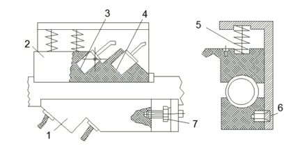
Figure 14. Portable ultrasonic flow transducer.
Measurement of air consumption in mines. Two piezoelements mounted on one wall of the mine workings out, direct acoustic emissions of small frequency (16-17 kHz) in opposite directions. Receiving piezoelements are located on another wall at large (5-6 m) distances from magnetostrictive type emitters.
Measurement of air speed in meteorological installations. Acoustic methods of measuring air speed are increasingly being introduced into meteorological practice. Special designs of converters designed for use in meteorological installations are being developed. In one of them, a piezoceramic radially polarized ring creates non-directional radiation in a plane perpendicular to the axis of symmetry.
Accuracy of flowmeters based on the movement of acoustic vibrations.
Let's list the main sources of errors: incorrect account of the effect of the velocity profile; change in ultrasound velocity in the substance being measured; parasitic acoustic signals; asymmetry of electron-acoustic channels. In addition to these sources, considered below, there are still errors introduced by the electronic circuit. They depend on the nature of the scheme and must be evaluated independently.
Incorrect rate profile. This error arises from the inequality of the average flow velocity of a measured medium of medium velocity along the path of displacement of acoustic oscillations. This inequality is taken into account by the correction coefficient, the precise value of which is difficult to determine. In the transition region from laminar to turbulent regime, the change in the correction factor is even more significant. Therefore, if a constant value of the correction factor is adopted for the calibration of the instrument, which corresponds to the average or other value of the flow, then at other costs an additional measurement error arises. With deformed flows, the true value of the correction factor is particularly difficult to determine. In this case, it is necessary to use flow transducers in which acoustic vibrations are directed along four chords (see Figure 1), or else to install a nozzle or confuser that straightens the velocity diagram.
The change in the speed of ultrasound. The speed of ultrasound c in liquids and gases depends on the density of the latter, which varies with the temperature, pressure, and composition or concentration (concentration) of the individual components. For liquids, the rate depends almost exclusively on temperature and content. The change in speed is essential for phase and time-impulse flowmeters. The error in measuring the flow from a change in c can easily reach 2-4% or more, since the error increases by 2% when the speed is changed by 1%. In flowmeters with radiation perpendicular to the axis of the tube, the error is half as large. In the case of frequency meters, a change in the speed value has very little effect on the measurement results.
Eliminate the effect of speed changes on the readings of phase and time-impulse flowmeters, as well as flowmeters with radiation perpendicular to the axis of the tube, by applying either appropriate correction schemes or by switching to a mass flow measurement. In the first case, an additional acoustic channel is introduced, perpendicular to the axis of the tube. For phase flow meters, the corresponding circuit is shown in Fig. 10. When measuring the mass flow, an additional piezoelectric element is used to measure the acoustic resistance of the medium, the proportional resistance of the substance (see Figures 11 and 13).
In converters with refraction, partial compensation of the effect is possible with the selection of the material of the evucoprovodule and the angle of its location. The compensation occurs because the temperature effect of measuring the refractive index on the time difference in phase and time-pulse flowmeters is counter-directed to the direct effect on the time of the change in velocity. But with significant changes in temperature, this method is ineffective because of the instability of the temperature coefficients. This method has several great possibilities when installing piezoelements outside the pipe and using liquid sound lines.
Parasitic acoustic signals. Parasitic acoustic signals can have a different origin. When the piezoelectric transducers are located outside the tube, a part of the acoustic energy is reflected from the tube-liquid interface and spreads as acoustic vibrations in the pipe wall. In this case, both longitudinal and transverse waves are formed. The latter can reach the receiving piezoelectric element before acoustic oscillations passing through the liquid. To exclude this, it is proposed to place piezoelements from different sides of the flange connection provided with a non-metallic gasket. Changing the shape of the pipe wall by creating thickenings, recesses or reflectors can also prevent the passage of spurious signals. Another source of parasitic signals is the appearance of a reverberation wave as a result of ultrasound reflections from the boundaries of a liquid with sound lines or piezoelements. The main meaning is the first parasitic signal arriving at the receiving piezoelectric element after double reflection first from the receiving element and then from the radiating element. Amplitude and phase of the reverberation wave differ from the amplitude and phase of the main wave. The receiving piezoelectric element perceives the resulting oscillations having their amplitude and phase. As a result, a phase shift is especially unpleasant for phase flow meters. In frequency flowmeters, the reverberation pulse can distort the front of the main pulse and prematurely turn on the frequency circuit. To eliminate this, it is suggested to shift the operating pulses with respect to the delay reflected by the electronic line. In addition, for the control of side reflections in small diameter pipes, the lining of the inner surface of the pipe with sound absorbing material (for example, fluoroplastic) helps.
Asymmetry of electron-acoustic channels. In the two-beam flowmeters, some asymmetry of the acoustic channels is unavoidable, which can cause a significant error in measuring the difference in the travel times in and out of the flow direction. The error in time is made up of the time error caused by the difference in the geometrical dimensions of the channels, due to the difference in the density of the measured substance.
The error from the geometric asymmetry can be compensated for at zero flow. But with the deviation of the speeds at which this compensation was made, the error will again arise, albeit to a much lesser extent. To reduce the error, both acoustic channels are placed as close as possible to each other. In this respect, circuits with channels arranged in parallel (see Figure 3, l) are better than circuits with intersecting acoustic channels (see Figure 3, m). The greatest error can arise in a circuit with three piezoelements (see Fig. 3, b). With small pipe diameters and low-frequency, and therefore poorly directed, radiation, when it is difficult to use a transducer of the angular type, special measures must be taken to maintain equality of temperatures in both channels. Thus, when measuring a small consumption of coal tar containing solid particles and moisture, the frequency of acoustic oscillations was taken to be 0.1 MHz, and the flow converter was made as shown in Fig. 194, d. To equalize the temperature in the channels remote from each other, they are drilled in a massive metal block covered with thermal insulation. Despite all the above measures, it is impossible to completely eliminate the asymmetry error with two-channel flowmeters. This is the reason for the predominant use of single-channel circuits at present, especially when accurate flow measurement is required. All that has been said about errors belongs not only to time pulses, but also to phase and frequency flowmeters, and in the latter, as a result of the already mentioned parasitic reverberation signals, an error may arise from the asymmetry of the fronts of the main pulses.
Doppler ultrasonic flowmeters.
Doppler flowmeters are based on a measurement that depends on the consumption of the Doppler frequency difference that occurs when the acoustic oscillations are reflected by flow inhomogeneities. The frequency difference depends on the velocity of the particle, which reflects the acoustic vibrations and the propagation velocities of these oscillations. With the symmetrical arrangement of the radiating and receiving piezoelements (Fig. 15) with respect to the speed or, equivalently, the axis of the tube, the angles of inclination are equal to each other.
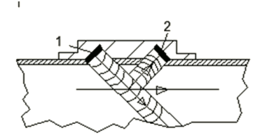
Figure 15. Scheme of Doppler flow converter (1,2 - emitting and receiving piezoelectric element)
Thus, the measured frequency difference can serve to measure the velocity of the reflector particle, i.e., to measure the local flow velocity. This brings the Doppler ultrasonic flowmeters closer to other flowmeters based on local velocity measurement. To apply them you need to know the relationship between the speed and the particle reflector and the average flow rate. In one paper, the possibility is examined of using the Doppler method to measure velocities at a number of points in the diametric section of the flow, ie, to obtain the velocity profile. For this purpose, the emitter sends acoustic pulses with a duration of 0.1-1 ?s and a frequency of 15-23 kHz to the stream. The receiving device opens only momentarily through the delay time after the sending of the pulse. By measuring the delay time, it is possible to obtain information on the velocity of particles at different points in the flow section.
With small pipe diameters (less than 50-100 mm) Doppler flowmeters are encountered, in which the lengths of the radiating and receiving piezoelements are equal to the internal diameter of the pipe. They react not to one, but to several local velocities of the particles located in the diametral plane of the tube section. An example of such a device is shown in Fig. 16. Piezoelements of barium titanate, 20 mm long, 6-5 mm wide, radiation frequency 5 MHz, Doppler frequency shift of about 15 kHz. The substance to be measured is a one-percent suspension of bentonite having particle diameters of not more than 0.1 mm. In order to eliminate the indeterminacy of the indications in the transition zone, the piezoelectric elements in the middle part were screened. Due to this, the ratio of velocities in the laminar zone increased sharply and practically became the same as in the turbulent zone, and the slope of the calibration line became the same in both zones. To prevent the formation of vortices in relatively large pockets where piezoelements are installed, the free space in them is filled with a foil made of polystyrene having the same acoustic resistance as water.
Now, in most cases, piezoelements from Doppler flowmeters are placed outside the pipe. This is especially necessary for the measurement of contaminated and abrasive substances, but additional errors due to, in particular, the refraction of the beam in the wall of the pipe, must be taken into account.
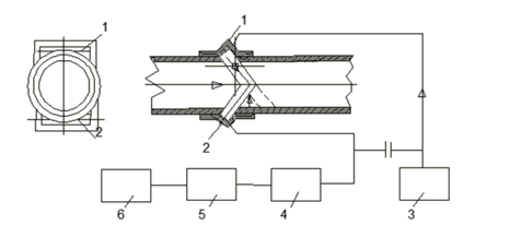
Figure 16. Scheme of Doppler flowmeter in small-diameter work (1,2-emitting and receiving piezoelements, 3-oscillator frequency of 5 MHz, 4-filter rectifier, 5-amplifier, 6-meter of Doppler frequency shift)
Compared to other ultrasonic flowmeters, Doppler flowmeters have the least accuracy, because the output signal represents a whole spectrum of frequencies arising from the shift of the original frequency by not one particle-the reflector, but a number of particles having different velocities. Therefore, the relative error in measuring the flow rate is usually not less than 2-3%.
Doppler ultrasonic flowmeters are becoming increasingly widespread. They are used mainly to measure the flow of various slurries, including pulps, suspensions and emulsions containing particles that differ in density from the surrounding substance. But natural heterogeneities (including gas bubbles), available in various liquids, are sufficient for the manifestation of the Doppler effect. In their absence, it is recommended to blow air or gas into the flow through a tube with holes 0.25-0.5 mm at a distance in front of the flow transducer. The consumption of the injected gas is 0.005 0.1% of the consumption of the measured substance.
Acoustic long-wave flowmeters (low frequency).
Unlike all previously considered ultrasonic flowmeters, long-wave acoustic flowmeters operate at a low (sonic) frequency. The scheme of the flow transducer of the prototype of such a flowmeter is shown in Fig. 17.
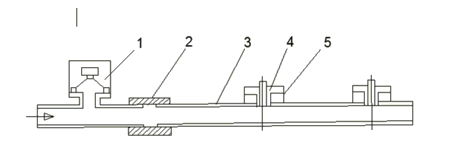
Figure 17. Low-frequency acoustic flowmeter.
The source of acoustic vibrations is the loudspeaker 1, mounted on the input section of a brass pipe with a diameter of 50 mm. This area is connected to a pipe 3 by means of a clutch 2 preventing transmission of vibrations and other disturbances, at which two microphones 4 are placed at a distance of 305 mm from each other. Their fastening is provided with spacers 5 of porous rubber. The receiving diaphragms of the microphones are flush with the inner walls of the tube. Acoustic vibrations produced by source 1 have a wavelength several times the diameter of the pipeline, which is favorable for eliminating high-frequency noise. This wave is reflected from both ends of the tube, as a result of which two waves move in the last towards each other. These two waves form a standing wave in the pipeline. The amplitude of the latter at the nodes is not zero, since the amplitudes of the waves moving in the opposite direction are not equal to each other. So, if the sound source 1 is installed up to the microphones, then the wave moving along the stream is formed from the addition of the wave formed by the source 1 and the wave reflected from the front end of the tube, while the return wave is only reflected from the output end and local resistances between him and the microphones. You should avoid installing microphones near the nodes of the standing wave. At a flow rate of = 0, the phases of the sinusoidal signals of both microphones are the same. With the advent of speed, a phase shift occurs, which increases with increasing velocity. The distance L between the microphones is chosen so that it is equal to the wavelength or half of it.
Conclusions
Of the four types of acoustic flowmeters considered, devices with ultrasonic oscillations directed along and against the flow were most widely used. Ultrasonic flowmeters with drift are very rarely used. They are much less sensitive than the first. Doppler instruments mainly serve to measure local flow velocities. Long-wave acoustic flowmeters have appeared recently, and there is no sufficient experience of their application.
Of the three methods for measuring the difference in the times of passage of ultrasonic oscillations along the flow and against it, the frequency-pulse method with a single-channel flow converter has become most widespread. It can provide the greatest measurement accuracy, and the reduced measurement error can be reduced to (0.5-1)%. Devices with even smaller error, up to ± (0,1 0,2)% are created, which makes it possible to use such devices as exemplary ones. Measuring circuits of two-channel flowmeters are simpler, but their accuracy is lower. Phase flow meters have the advantage over frequency ones when it is necessary to measure low velocities up to 0.02%, as well as for measuring contaminated media.
With a deformed velocity field due to the insufficient length of the straight section of the pipeline, a large additional error may occur. To eliminate the error, you must use a nozzle or confusor, leveling profile, or a flow transducer, in which acoustic vibrations are directed not in the diametric plane, but along several chords.
The main area of application of ultrasonic flowmeters is the measurement of the flow of various liquids. They are particularly suitable for measuring the flow rate of non-conductive and corrosive liquids, as well as oil products.
Used Books:
1. Kremlevsky P. P. Flowmeters and counters of the amount of substances: Handbook: Book. 2 / Under the Society. Ed. E. A. Shornikova. - 5 th ed., Pererab. and additional. - SPb .: Politechnica, 2004. - 412 s