
Abstract
Content
- Introduction
- 1.Relevance of the topic
- 2.The purpose and objectives of the study, the planned results
- 3.Development and research of the optoelectronic node
- 3.1.Time interval measurements
- 3.2.Modeling of electronic laser rangefinder
- 4.Overview of the block diagram of the device
- 5.Development of the design of the device (system)
- Conclusions
- List of sources
Introduction
In this master's work, a laser rangefinder is developed for a field monitoring system for natural gas leaks. This device allows significantly improve the accuracy of determining the parameters of natural gas leaks and on the basis of these data take the necessary adequate measures to eliminate leaks of natural gas. As a method of measuring natural gas leaks, a non-contact optical measurement method range. The result of measurements is planned to be established at multiple observations.
1. Relevance of the topic
With the onset of the 21st century, mankind was confronted with the problem of the limited nature of resources according to various forecasted data, explored the resources of oil gas will be exhausted in the next 30-40 years, this poses the problem of economical expenditure of available natural resources. Depressurization pipeline leads to non-production losses of natural gas, the reduction of these losses is associated with the control of the pipeline in a timely manner detection of gas leaks and their elimination. In the developed gas leakage detection system, the accuracy of the solution of the problem depends on the exact measuring the distance between the hardware units of the leak detection equipment. The range-measuring device included in such a equipment allows to significantly increase the accuracy of determining the parameters of natural gas leaks and on the basis of these data to take the necessary adequate measures to eliminate leaks. Development of a range-finding device for the system The definition of leaks should be considered necessary and relevant.
2. The purpose and objectives of the study, the planned results
Purpose — the development of a range-measuring device to ensure an improved measurement of methane leakage from the pipeline, by taking into account the length of the optical path.
The main objectives of the study:
- Analyze existing methods and means of measuring range; Choose a method that best achieves the goal, taking into account the specific features of leakage measurement.
- Develop a structural diagram of the device that implements the chosen method, choose the principal solution of the individual structural elements of the device;
- Carry out engineering calculations of the device nodes;
- Assess the improvement in the accuracy of measuring natural gas leaks using a distance measuring channel. Estimate the metrological characteristics of the distance measuring channel.
Object of study —instrument (measuring channel) range measurement as part of a complex for measuring natural gas leaks from main pipelines.
Subject of study — methods and means for measuring the length of the optical path of a natural gas leakage meter in the field.
As part of the master's work, it is planned to receive topical scientific results in the following areas:
- development of algorithms for the detection of leaks of natural gas from the main gas pipeline, taking into account the length of the optical path.
- Development of the structure of natural gas leaks containing a channel for measuring the range of the optical path and providing an increase in the accuracy of measuring leakage.
3. Development and research of the optoelectronic node
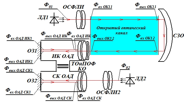
Figure 3.1–
Scheme of identification of optical signals in the range channel
They are accepted both for ensuring the range measurement by the phase method and processing of the optical signal by a photodetector an optical flow is modulated by optical components without dispersion. Under these assumptions, an estimate is made of the amplitude of the output signal. To provide visualization of the optical signal of the measuring range, the emitter wavelength is 0.65 μm. This corresponds to a red beam that is clearly visible when making settings. As a source of radiation is adopted semiconductor laser HLDP 650-A.
The operating mode is pulsed;
The average value of the current is 8.75 mA;
The module frequency is 4000 kHz;
The modulation current amplitude is 35 mA;
The average LD flow is 1.25 mW;
The amplitude of the stream is 5.0 mW;
To provide a mode of excitation of the power laser, namely, the pump current is formed by a precision controlled current source;
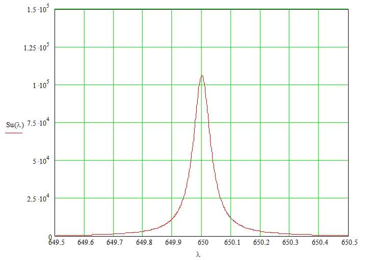
Figure 3.2- Spectral radiation density of a semiconductor laser.
To correct the optical signal parameters, a two-lens telescopic lens.
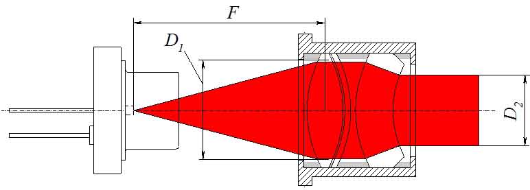
Figure 3.3 –Collimating two-lens objective
Calculation of the spatial parameters of the optical signal is performed by the source. An optical system (lens-attachment) is used to correct the divergence angle of a semiconductor laser.
3.1.Time interval measurements
The phase delay is measured by the double integration method
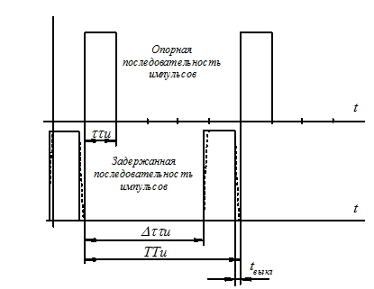
Figure 3.1.1 – Time interval measurements [1]
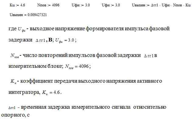
The output voltage of the integrator is set:
The time of the direct movement of the integrator measuring phase is determined:
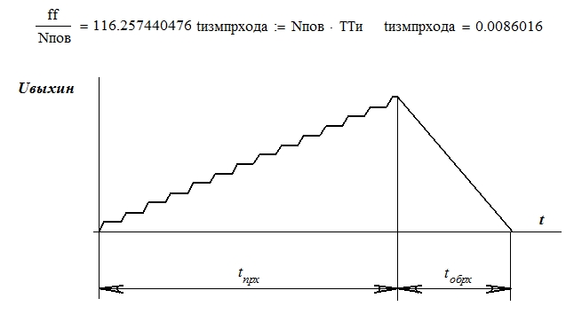
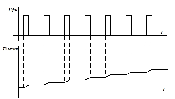
Figure 3.1.3–
Change of voltage on the integrator in the modes of accumulation and discharge
The discharge process has a different duration. It starts with the voltage accumulated at the integrator, for a finite number of input pulses, the duration of which carries information about the range. The value of the accumulated charge is functionally determined by the range value. The discharge is performed with the same time constant and ends with a transition through 0. At the same time, the duration of the discharge process is functionally dependent on the range. With increasing range, the discharge time increases. Essentially, the range is transformed into a time interval – the duration of the discharge process. To convert the time interval into the code, the time interval is filled with the number of counting pulses. Counting the number of pulses is provided by a binary counter.
3.2 Modeling of electronic laser rangefinder
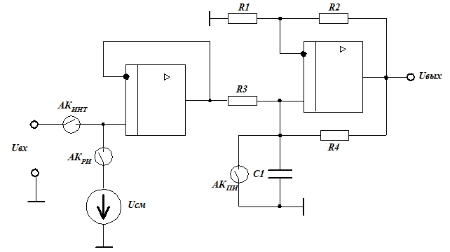
The integrator circuit with analog keys included in the respective phases: AKint – integration, ACry – discharge of the integrator, AKpi – preparation of integration.
[3]
Figure 3.2.1 Scheme for converting time intervals into a range code
Resolution of the meter – 1.5 cm;
The clock frequency of counting pulses is 19.2 MHz;
The number of bits of the counter is 15;
[4]
4.Overview of the structure of the laser rangefinder for the field control system
As a source of radiation, one should choose a semiconductor laser with a wavelength λ=0,645 μm, which corresponds to the red color, that is, the ray is visible, providing visual control. Silicon photodiodes are used as a receiver. To ensure effective suppression of the random component of error, the result should be obtained by accumulation NΔt, where Δt – this is an interval equivalent to the phase difference.
Interval storage function Δt are realized with the help of an integrator that ensures the conversion of the accumulated sum of the phase delay intervals into a voltage. Due to the use of the double integration method, the accumulated voltage at the integrator is converted into a time interval. The time interval is converted to the number of pulses using a high-frequency pulse train and a binary counter. In the device it is necessary to introduce pulse shapers, by means of which the improvement of the edges of the pulse signals is provided. Taking into account the above, the structural diagram of the device has the form (Fig. 2);
The radiation source is a semiconductor laser, which must operate in a pulsed mode. The repetition frequency is 200 Hz. Control of the operating mode is performed by the clock pulse generator (GTI). From the clock generator, the signal is fed to the semiconductor laser control device (ULL), then the signal is fed to a semiconductor laser (PL) circuit. The output signal of the semiconductor laser passes through a semitransparent mirror (PZP) and is divided into two streams: the main one (output to the optical path) and a second flux, 3-5% of the original, which is fed into the feedback loop to the device (FPU1). With this feedback, the pulse amplitude is provided.
The signal reflected from the reflector L (25-250m), enters the lens. Then on the photodiode (FPU2). The pulsed current output signal is converted into a voltage signal and a pulse shaper (FI) is applied to the trigger. The output signal from the pulse shaper is fed to the UFIS. The signal from the clock generator is fed to the first input of the UFIS. The incoming signal from the FI is behind the reference signal (from the clock pulse generator). The coincidence circuit generates a pulse whose duration is equal to the delay time of the second signal. This signal is fed to the information signal generation device (UFIS), and then to the integrator. And also the signal from the coincidence circuit is fed to the control device (UU), which counts the number of signals. The process of pulse integration continues during the arrival of 4096 pulses.
After the integrator receives 4096 pulses (the pulses are counted as a counter), it is put into the discharge (reverse) mode. In this case, the integrator input is connected to the common bus. The control device sends a signal to the first input of the AND element, the duration of which is equal to the discharge time of the integrator. The second input receives short pulses from the high-frequency generator (GWP). The number of short pulses transmitted through the "I" is counted by the binary counter St2. The moment the integrator reaches the voltage 0 is determined by an electronic comparator whose inputs are fed with signals:
- from the integrator to the first input;
- on the second input there is a voltage equal to 0.
As soon as the voltage difference changes sign - the output of the comparator forms a voltage drop from 0 to a high level.
On the front of this signal stops counting the number of pulses by the binary counter St2. The control unit on the microcomputer receives a signal "End of measurements" and a binary code from the counter. The microcomputer perceives the signal "End of measurements" and it enters the microcomputer interrupt system. Interrupt handling initiates the data entry program. The output binary code is entered into the microcomputer memory.
The program for processing the variable "Duration of the optical channel L" assigns the value of the binary code. The same program outputs the output of the microcomputer (either the "Start" of the next measurement, or "End of measurement"). At "Start", St2 is set to the initial state as directed by the control device. With the first signal from the generator of sinusoidal signals, the formation of the results of new observations begins.[5]
Figure 4.1 – The block diagram of the laser rangefinder operation
(animation: 5 frames, 5 repetition cycles, 60 kilobytes)br>
5.Development of the design of the device (system)
The device is designed in the form of two blocks and a reflector (theodolite) of the optical signal. The emitter unit consists of a 650 micron semiconductor laser modulated by the device range finder. The second unit is presented as a receiver for receiving an optical signal which originates from the receiving lens, The signal is then absorbed by a photodiode that converts the optical signal into a current.
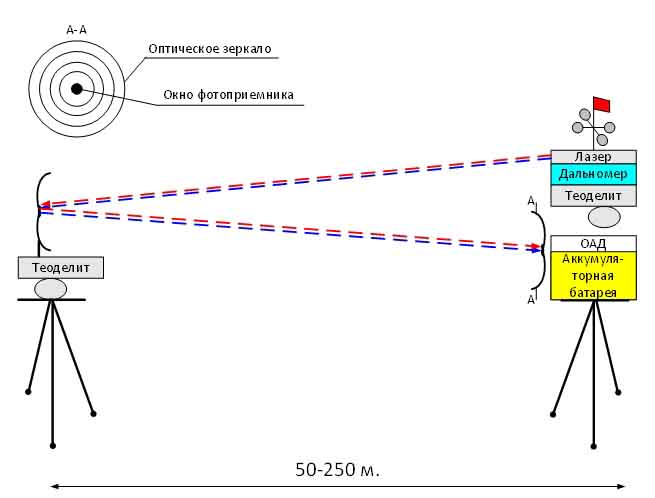
Figure 5.1 –The design solution of the measurement system is presented in the form of two blocks and a reflector of the signal in the form of a theodol device. [6]
Conclusions
In this master's work, I considered a laser rangefinder for a field monitoring system for natural gas leaks. Direction of further research and development: this project can be used as a basis for detailed design channel measuring the range of the source. The introduction of such a channel will ensure the measurement of leakage with an accuracy of 1.6%. The use of such a device is very relevant and economically justified in the context of the global energy crisis.
Список источников
- Климков Ю.М. Основы расчета опто-электронных приборов с лазерами. – М.: Сов. радио, 1978. – 264 с
- Федорков Б.Г., Телец В.А., Дегтяренко В.П. Микроэлектронные цифро-аналоговые и аналого–цифровые преобразователи. – М.: Радио и связь, 1984. – 120 с., ил. -
(Массовая б-ка инжеера "Электроника", вып. 41). Измерение фазовых запаздываний выполняется методом двойного интегрирования
- Туз Ю.М. Структурные методы повышения точности измерительных устройств. – Киев: Выща школа, 1976. –
Метод двойного интегрирования при фазовых измерениях
- Расчет электронных схем. Примеры и задачи: Учеб. пособие по спец. электрон. техники Г.И. Изъюрова, Г.В. Королев, В.А. Терехов и др. – М.: Высш. шк., 1987. – 335 с.
- Карасик В.Е.Лазерные информационные приборы. – М.:, Из-во МВТУ им Н.Э. Баумана, 1986. – 68 с. илл
- Перегуд Е.А., Д.О. Горелик Инструментальные методы контроля загрязнения атмосферы. – Л.: Химия, 1981. – 384 с
- Заказнов Н.П. Прикладная геометрическая оптика.– М.: Машиностроение, 1984.– 184 Элементы о. систем: линзы, зеркала,
диафрагмы, призмы, клинья, пластины…Распространение излучения (170), эффективность зрения, связь единиц, коэф. пропускания о. системы, прохождение потока через фильтр.
- Креопалова Г.В., Лазарева Н.Л., Пуряев Д.Т. Оптические измерения: Учебник для вузов по специальностям “Оптикоэлектронные приборы” и “Технология оптического приборостроения”/
Под общ. ред. Д.Т. Пуряева. – М.: Машиностроение, 1987. – 264
- Прикладная оптика: Учебник для оптических специальностей вузов. М.И. Апенко, А.С. Дубови Г.В. Дурейко и др.; Под общ. ред. А.С. Дубовина, – 2-е изд., перераб. и доп. – М.: Машиностроение, 1992. – 480
- Бельский А.М., Корнейчик Т.М., Хапалюк А.П. Пространственная структура лазерного излучения. Под ред. А.П. Хапалюка. – Минск, Изд-во БГУ, 1982. – 198 с
- Зуев В.Е. Распространение лазерного излучения в атмосфере.– М.: Радио и связь, 1981. – 288 с.
- Салль А.О. Инфракрасные газоаналитические измерения: Погрешности и информационная способность инфракрасных газоанализаторов.– М., Издательство стандартов, 1971. – 100 с.
- Бреслер П.И. Оптические абсорбционные газоанализаторы и их применение. – Л.: Энергия. Ленингр. Отд-ние, 1980.– 164 с.
- Избирательное поглощение лучистой энергии в газах. Параметры полос поглощения(СО2, СО, N2O, CH4). Теория построения оптико-акустических газоанализаторов. Промышленные ОА газоанализаторы.
- Уорк К., Уорнер С.Загрязнение воздуха. Источники и контроль. Перевод с англ. Под ред. Е.Н. Теверовского. – М.: Мир, 1980. –540 с.
- Климков Ю.М. Основы расчета опто-электронных приборов с лазерами. – М.: Сов. радио, 1978. – 264 с
- Федорков Б.Г., Телец В.А., Дегтяренко В.П. Микроэлектронные цифро-аналоговые и аналого–цифровые преобразователи. – М.: Радио и связь, 1984. – 120 с., ил. - (Массовая б-ка инжеера "Электроника", вып. 41). Измерение фазовых запаздываний выполняется методом двойного интегрирования
- Туз Ю.М. Структурные методы повышения точности измерительных устройств. – Киев: Выща школа, 1976. – Метод двойного интегрирования при фазовых измерениях
- Расчет электронных схем. Примеры и задачи: Учеб. пособие по спец. электрон. техники Г.И. Изъюрова, Г.В. Королев, В.А. Терехов и др. – М.: Высш. шк., 1987. – 335 с.
- Карасик В.Е.Лазерные информационные приборы. – М.:, Из-во МВТУ им Н.Э. Баумана, 1986. – 68 с. илл
- Перегуд Е.А., Д.О. Горелик Инструментальные методы контроля загрязнения атмосферы. – Л.: Химия, 1981. – 384 с
- Заказнов Н.П. Прикладная геометрическая оптика.– М.: Машиностроение, 1984.– 184 Элементы о. систем: линзы, зеркала, диафрагмы, призмы, клинья, пластины…Распространение излучения (170), эффективность зрения, связь единиц, коэф. пропускания о. системы, прохождение потока через фильтр.
- Креопалова Г.В., Лазарева Н.Л., Пуряев Д.Т. Оптические измерения: Учебник для вузов по специальностям “Оптикоэлектронные приборы” и “Технология оптического приборостроения”/ Под общ. ред. Д.Т. Пуряева. – М.: Машиностроение, 1987. – 264
- Прикладная оптика: Учебник для оптических специальностей вузов. М.И. Апенко, А.С. Дубови Г.В. Дурейко и др.; Под общ. ред. А.С. Дубовина, – 2-е изд., перераб. и доп. – М.: Машиностроение, 1992. – 480
- Бельский А.М., Корнейчик Т.М., Хапалюк А.П. Пространственная структура лазерного излучения. Под ред. А.П. Хапалюка. – Минск, Изд-во БГУ, 1982. – 198 с
- Зуев В.Е. Распространение лазерного излучения в атмосфере.– М.: Радио и связь, 1981. – 288 с.
- Салль А.О. Инфракрасные газоаналитические измерения: Погрешности и информационная способность инфракрасных газоанализаторов.– М., Издательство стандартов, 1971. – 100 с.
- Бреслер П.И. Оптические абсорбционные газоанализаторы и их применение. – Л.: Энергия. Ленингр. Отд-ние, 1980.– 164 с.
- Избирательное поглощение лучистой энергии в газах. Параметры полос поглощения(СО2, СО, N2O, CH4). Теория построения оптико-акустических газоанализаторов. Промышленные ОА газоанализаторы.
- Уорк К., Уорнер С.Загрязнение воздуха. Источники и контроль. Перевод с англ. Под ред. Е.Н. Теверовского. – М.: Мир, 1980. –540 с.