
Abstract
Contents
- Introduction
- 1. Theme urgency
- 2. Goal and tasks of the research
- 3. Review of research and development
- 3.1 ОOverview of international sources
- 3.2 Overview of national sources
- 3.3 Overview of local sources
- 4. Analysis of the control object
- 5. Development of a structural diagram of the management system
- 6. Modeling of the management system and analysis of regulatory quality indicators
- Conclusion
- References
Introduction
The current state of the theory and practice of automatic regulation is characterized by intensive development and the ever increasing use of new and new methods of management. Robust control, control with the predictor of Smith (Internal Model Control), control with fuzzy logic controllers, control using neural networks and also control based on the prediction of the state of the object can be safely referred to such methods. The greatest interest in recent times is manifested in so-called object management based on the use of predictive models, which combines the advantages of using Smith's predictor and the advantages of optimal control in the presence of constraints on control and on the variables and spaces of the object. In this case, the method does not distinguish between linear and nonlinear control objects; to linearize the characteristics of the object are resorted only to simplify the solution of the problem of optimal control in accordance with the chosen system quality functional.
1. Theme urgency
The use of modern automatic control systems in the industry requires more and more qualified specialists. One of the ways to improve skills is using laboratory stands and automation models. This helps to systematize the theoretical knowledge obtained, technically implement various control laws and methods for identifying objects. The subject of this work of the bachelor is some results of the research, consisting in testing the control method with prediction on the laboratory model of the aerodynamic object. The control object is an aerodynamic object, on the basis of which an automatic control system has been developed. It consists of a base to which a tube is attached. A pin is inserted into it, which can freely rotate along the angle α. On top of the pin there is a fastening, which makes it possible to rotate along the angle β.
2. Review of research and development
The aim of the paper is to apply a control method based on the prediction of the state of an object using an object model called the Model Predictive Control (MPC) literature. This is an important task, because at present the scope of practical application of MPC methods is significantly increased due to a relatively simple basic feedback scheme, combined with high adaptive properties of the system.
The main objectives of the study:
- Analyze the control object and make a mathematical model of the object
- Selection of a range of automation equipment, such as: angle sensors, DC motors and microcontrollers.
- Development of a structural control scheme and the synthesis of control algorithms.
- Check the operation of the control system by modeling the control system and analyze the quality of the regulation.
3. Review of research and development
There are many different modern regulatory systems, such as a control system with Smith's predictor, neural networks, a fuzzy logic control system, and a forecast-based control system. All management systems have merits and demerits, but for the given object of management the most suitable is the choice of the control system based on the forecast of the state of the object.
3.1 Overview of International Sources
In foreign space, there is the largest number of sources on the topic of forecast management. Most of the books and publications are published in German.
The book contains an introduction to predicate control Title: Matlab 5 für Ingenieure. Systematische und praktische Einführung (Sonstige Bücher AW) Authors: A Biran, M Breiner Publisher: Addison-Wesley; Auflage: 3. überar. u. erw. Aufl. (15. Januar 1999) ISBN: 978-3827314161 Number of Pages: 378
This book is fully devoted to Model Predictive Control. The second edition of this book provides the most complete familiarization with theoretical and practical aspects.
Name: Model Predictive Control Authors: Camacho, Eduardo F., Bordons Alba, Carlos Publisher: Springer, 2007 ISBN: 978-0-85729-398-5 Number of pages: 296
3.2 Overview of national sources
In the Russian-language space there are also articles on the subject of forecast management, but due to the fact that this method of management is not too common, it is rather difficult to find scientific publications with useful information.
Krasovsky A.A. Automatic flight control systems and their analytical design / Krasovsky AA - Moscow: "Science", 1973. The book contains a systematic presentation of the purpose, principles of construction and operation of a number of typical control systems for aircraft and helicopters and analysis of processes in the control circuits of these aircraft.
Ananyev I.V. Dynamics of aircraft design / Ananyev I.V. - M., 1972. - 415s. The book outlines methods for calculating the vibrations of elastic systems used in the aviation and engineering industries.
3.3 Overview of local sources
Within the framework of Donetsk National Technical University (DonNTU) several works with similar subjects were found.
The work of Master DonNTU Kosyanenko Lilia Fedorovna - Research and development of algorithms for the operation of automated systems for monitoring the state of technological objects with nonlinear dynamics [3]. In the framework of this paper, the dynamic characteristics of the control system in transition modes of operation are considered.
Work of Master DonNTU Bezruk Alexander Anatolevich - Research and development of the system of stabilization of the flight of 3-copter over rough terrain [x]. In work the existing methods of realization of unmanned aerial vehicles are considered.
The work of master DonNTU Perebeynos Valeriy Valerievich - Development and investigation of the electronic system of stabilization of the flight of a quadrocopter [x]. The paper considers the development and investigation of the electronic system for stabilizing the flight of a quadrocopter.
4. Analysis of the control object
The control object is a simplified model of the aerodynamic object (helicopter). Taking into account the general idea of the helicopter flight, a model is created which, due to the attraction force of the main and tail propellers, allows changing the inclination of the helicopter relative to the horizon (with the flight forward or during braking), as well as changing the direction of flight.
An automated aerodynamic control system with two degrees of freedom must have an actuator that moves the airflow control object along each of the axes. The opamp must have a stable platform in the base and be able to rotate along the X, Y, Z axes. When turning in one of the planes, the angle of inclination in the other plane must be maintained. To control the control object, you need the rotation angle sensors in each plane, which allow you to transfer information about the object to the microcontroller to monitor and further control the ACS. Figure 1 shows the aerodynamic control system, which will simulate a full-fledged model with two degrees of freedom.
The aerodynamic model consists of a platform (1) on which a hollow tube (2) is fixed. A pin (3) is inserted into it, on which a fastening is mounted to ensure a vertical rotation of the pin (4). The pin (3) freely rotates horizontally and does not change the angle of inclination with respect to the platform.
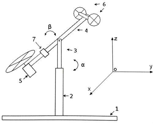
Figure 1 - Aerodynamic model with two degrees of freedom
At the edges of the pin (4), DC collector motors are mounted, on the shaft of which plastic containers are installed, which create an airflow and thus move the pin (4) in space. The engine (5) is fixed so as to move vertically (up and down). On the opposite side, there are engines (6) with axes of rotation to the outside, which allow horizontal movement (left and right). At the edges of the pin (3) are located angle sensors, which will transmit information about the state of the op-amp in the MK for future use.
The system is balanced in such a way that the motor (5) on the pin (4) has been lowered down when the engine is off (6), and when it is on, it rises to the level of the horizon. For this purpose a special load (7) is fixed on the pin (4).
Thus, the measured values are the rotation angle α and the rotation angle β. To determine the angle of inclination α, the sensor located on the pin (3) from above is used. Given the physical properties of the op-amp, the angle of inclination is in the range of 0 to 85 degrees. The turn sensor located at the bottom of the pin (3) determines the angle of rotation β in the range from 0 to 200 degrees.
5. Development of a structural diagram of the management system
In this paper, an aerodynamic object is considered that consists of a beam that rotates freely both vertically and horizontally with the help of motors. The angle of rotation in the horizontal and vertical planes can be changed by controlling the voltage that is applied to the motors, which in turn changes the speed of the blades in the vertical and horizontal planes.
The position of the beam is described by four process variables: a horizontal α vertical β beam angle that is measured by rotational sensors that are located at the fulcrum and two additional state variables, angular velocities of the horizontal and vertical angles that are calculated programmatically.
The system of equations will have the following form:
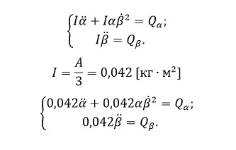
Thus, a mathematical model of the control object is obtained, which is a system of equations.
The ACS that is developed in this paper can be represented in the form of a structural diagram, which is shown in Figure 2. This structural diagram is a classical model of control in production.
There are 3 engines in the system that have non-linear static characteristics. The given system has 2 inputs - defining the angles of rotation and 2 outputs - the angles of rotation of the beam in the horizontal and vertical planes. In the system, there is a link between the state variables α and β (Figure 3), so the object is multidimensional.
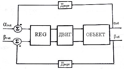
Figure 2 - Block diagram of object management
However, a multidimensional object can be regarded as a first approximation as two systems: firstly, the dependence of the moment of inertia of the beam on its slope for the dimensions of the model is negligible, and secondly the mutual influence of the propellers is also insignificant. Thus, the object in Figure 2 can be considered as 2 independent objects, that is, the object for the horizontal component of the motion (Figure 3), and the object for the vertical component of the motion (Figure 4).
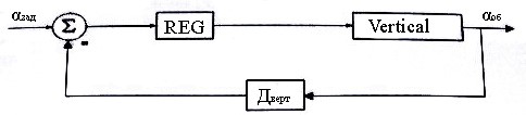
Figure 3 - Structural diagram of control of the horizontal component of the object
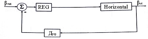
Figure 4 - Structural diagram of the vertical component control of the object
6. Modeling of the management system and analysis of regulatory quality indicators
We will construct the modeling circuit in the Simulink package on the basis of the structural control scheme for the aerodynamic object. The model is shown in Figure 5.
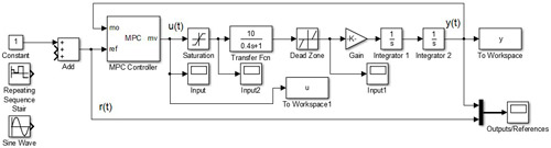
Figure 5 - Simulink simulation scheme
We perform the simulation of the system for various input effects:
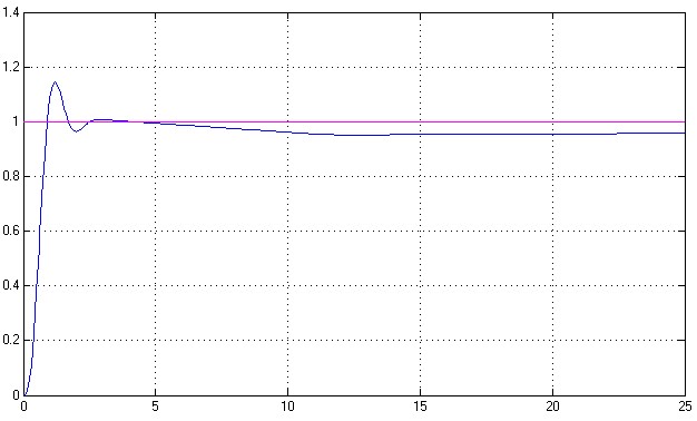
Figure 6 - Reaction of the system at the setting action - constant
It can be seen from the graph that the transient response has overshoot, but it is within the normal range. The time of the transient is 2 seconds.
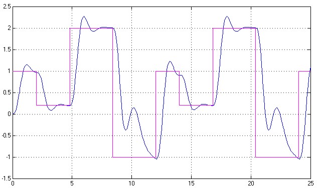
Figure 7 - The reaction of the system to the input sign-variable piecewise constant effect
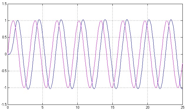
Figure 8 - System response to sinusoidal input
In order to take into account the small interference of the sensor, we add white noise to the simulation circuit. This block must be located in the feedback loop. We simulate the situation when, during the operation of the object, it will be impacted by a jerk in the form of a push, with a duration of 0.4 seconds and see how the system reacts to such an impact.
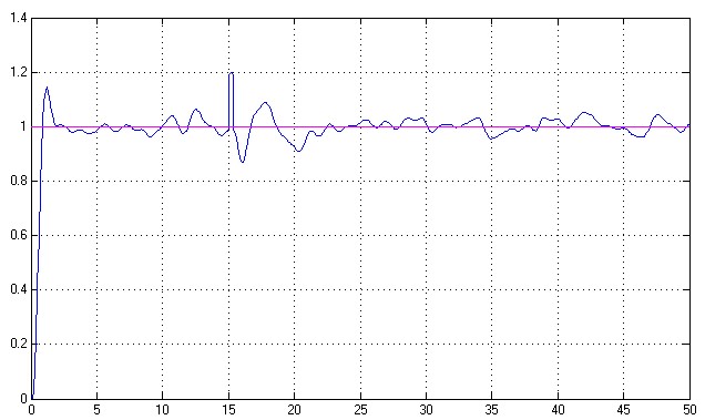
Figure 9 - System response to external interference with a single exposure
The graph shows that 15 seconds after the start of the system's operation, an impulsive disturbing effect acts on it, which the system promptly processes and quickly comes to a steady state. Also on the chart you can see how it reflects the noise from the potentiometers - turn sensors and despite this the system is still in steady state.
An attempt to use the PID controller, whose parameters are tuned in the Matlab / Simulink system using the linearized model, to control the real object containing nonlinear elements (deadband and constraints) leads to disappointing results. Using a PID controller to control an aerodynamic object is not suitable.
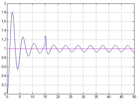
Figure 10 - Transient process in a control system with a PID controller
Conclusion
In this project, the task of automating the control of an aerodynamic object is solved. All the main characteristics and design of the helicopter model are presented. The review of the existing automatic control systems for the selected model of the aerodynamic object is carried out. A functional scheme has been developed, taking into account the composition and structure of the functional nodes of the control system allocated at the stage of setting the design assignment. A mathematical description of the ACS is obtained by an aerodynamic object. The functional scheme is constructed and described. The coefficients for the MPC regulator are selected. Modeling of the ACS in the Matlab & Simulink package was performed. The results of the simulation prove the operability of the automatic control system and the possibility of using the developed system for aerodynamic objects.
References
- Хорхордин А.В., Олейников Е.А., Система автоматического управления аэродинамическим объектом на основе ПИД-регулятора. Збірка наукових праць SWorld за матеріалами міжнародної науково-практичної конференції «Наукові дослідження і їхнє практичне застосування. Сучасний стан і шляхи розвитку - 2011 » 4-15 жовтня 2011. Том 4 «Технічні науки», стр. 66 – 69. Одеса: Черноморье, 2011.
- Biran, A. MATLAB 5 für Ingenieure: Systematische und praktische Einführung / Adrian Biran: Moche Breiner [Übersetzung aus dem Amerikan. Stefan Braun; Harald Häuser]. – 3.Auflage – Bonn [u.a.] : Addison-Wesley-Longman,1999.- 542 p.
- .Гессоу А. и Мейерс Г. Аэродинамика вертолета / Гессоу А. и Мейерс Г. – М.: Оборонгиз, 1954, - 256с.
- Красовский А.А. Системы автоматического управления полетом и их аналитическое конструирование / Красовский А.А. – М.: «Наука», 1973г.
- Ананьев И.В. Динамика конструирования летательных аппаратов / Ананьев И.В. – М., 1972г. – 415с.
- Рафиков Г.Ш. Современная теория управления дискретных динамических систем / Рафиков Г.Ш. – Донецк: «Норд-пресс», 2005г., -345с.
- Дейч А.М. Методы идентификации динамических объектов / Дейч А.М. – М.: Энергия, 1979. – 240с.
- Гроп Д. Методы идентификации систем / Гроп Д. – М.: Мир, 1979. – 302с.
- Баранов В.Н. Применение микроконтроллеров AVR: схемы, алгоритмы программы / Баранов В.Н. – М.: «Додека - XXI», 2004. – 288с.
- Трамперт В. Измерение, управление и регулирование с помощью AVR микроконтроллеров / Трамперт В. – К: «МК - пресс», 2007г. – 208с.
- М.И. Макаров, А.В. Жадан, А.А. Зори Надежность электронных устройств автоматики, информационных и компьютерных систем / М.И. Макаров, А.В. Жадан, А.А. Зори – Донецк, ДонГТУ 1996.
- Н.Н. Акимов, Е.П. Ващуков Резисторы, конденсаторы, трансформаторы, дроссели, коммутационные устройства РЭА: Справочник / Н.Н. Акимов, Е.П. Ващуков Минск 1994г.
- Р.М. Терещук, К.М. Терищук, С.А. Седов Полупроводниковые приемно - усилительные устройства. Справочник радиолюбителя / Р.М. Терещук, К.М. Терищук, С.А. Седов – Киев.: Научный совет. 1982г.
- . Теория надежности и радиоэлектронных систем в примерах и задачах / Под ред. Р.В. Дружинина. – М.: Энергия, 1976. – 448с.
- Косьяненко Лилии Федоровны - Исследование и разработка алгоритмов работы автоматизированных систем контроля состояния технологических объектов с нелинейной динамикой [3].
- Безрука Александра Анатольевича - Исследование и разработка системы стабилизации полета 3-коптера по пересеченной местности [х].
- Перебейноса Валерия Валериевича - Разработка и исследование электронной системы стабилизации полёта квадрокоптера [x].