
Investigation of the effect of camera calibration parameters on the accuracy of constructing three–dimensional models
Content
- Introduction
- 1. Relevance of the topic.
- 2. Analysis of the study of the problem.
- 3. The purpose and objectives of the study.
- 4. The order of the research.
- 5. Field work.
- 6. Finding the parameters of a non–metric chamber and determining their influence on the accuracy of constructing a three–dimensional model.
- 6.1 Finding the parameters of a non–metric chamber, distortion.
- 6.2 Processing of images, construction of a three–dimensional model.
- 6.3 Comparative analysis of surfaces.
- ╤onclusions
- List of sources
Introduction
Photogrammetric methods have been and remain one of the most important components of highly productive and profitable technologies in geodetic production. For a long time, photogrammetric methods remained the main ones for drawing up topographic plans, creating maps, also used in architecture, during the filming of buildings and structures, were used in surveying and mining for the surveying of quarries. Recently in photogrammetry there has been a decline in view of the following reasons. The filming equipment is obsolete and can be changed, due to the complete absence of its production. In a similar situation, there is a desk processing that is performed on universal photogrammetric devices. Another reason is the appearance of laser scanners, which rapidly replace photogrammetric methods from the list of the most used in geodetic production [1].
1. Relevance of the topic.
A new step in the development of photogrammetry as a science is the emergence and spread of digital
technologies. The advent of digital technology has simplified the shooting and cameral processing,
which is done at photogrammetric stations, which are located on personal computers. At the moment,
in the software market, there are photogrammetric stations, the possibility of which is expanding
to the possibility of constructing three–dimensional models for a set of digital photographs [2].
Programs were considered, such as Agisoft PhotoScan
, Contex Capture
from Bentley,
openMVG
, VisualSFM
, ArcheOS 4
, ArcheOS 5
and
insight3d
.
In this work, the choice is stopped on the software product Agisoft PhotoScan
but also it can be considered promising
Contex Capture
from Bentley.
To collect data, unmanned aerial vehicles (UAVs) with digital cameras installed on them are used, which is a cheaper way compared to laser scanners. The method promotes an increase in the productivity of geodetic production. But in turn leads to the appearance of errors [3].
Following from the foregoing, the problem of finding UAV camera parameters in order to exclude non–fulfillment of the collinearity principle (the central projection of the image is violated) on the images for further image processing and construction of the 3D model becomes urgent. The task is to establish the possibility of using this method in production.
2. Analysis of the study of the problem.
Of great importance for the solution of the scientific problem posed in the master's thesis are researches of scientists: V. Glotov, V. Chizhevsky, A. Katushkov, B. Pryakha, D. Titov, T. Shirabakina, L. Zhimbueva, I. Kunina, S. Gladilin, D. Nikolaev concerning the method for determining the distortion of digital cameras; Yu. Lashchenov, V. Kasyanuk, A. Zavorotny and S. Guzevich made a contribution to the study of mathematical methods for processing digital data of the approximation problem; in turn, A. Postelnyak, E. Smirnov, M. Lazerko, O. Korchagina, I. Tuktarov, A. Leonov, A. Aleinikov, A. Bobkov , E. Yermchenko, A. Klimenko, P. Frolov, Yu. Blokhinov, M. Verkeenko, V. Gorbachev, S. Skryabin, S. Kadnichansky, B. Novakovsky, A. Prasolova, R. Permyakov worked on the development of techniques for creating 3D models and estimating the accuracy of the heights of digital terrain models; S. Mogilnyi, A. Sholomitsky, A. Lunev, A. Katushkov, B. Pryakha, F. Remondino, C. Fraser, A. Bykov, V. Nikitin, A. Sementsev, R. Gelman, Ye. Voronin, G. Shekhovtsov, R. Shekhovtsova, Yu. Raskatkin – features of calibration of aerial cameras from images of a flat polygon; A. Zhuravlev, E. Goshin, V. Fursov, – automatic calibration of a digital camera; Yu. Blokhinov, A. Guk, M. Lazerko developed algorithms for the formation of a digital surface model and a texture coating in ground photogrammetry; M. Shevnya – use of unmanned aerial vehicles for obtaining remote sensing materials.
3. The purpose and objectives of the study.
The purpose of the study is to determine the effect of camera calibration parameters on the accuracy of constructing three–dimensional models.
The object of the study is the self–calibration technology of a non–metric chamber.
The subject of the study is a three–dimensional model built in the program Agisoft PhotoScan for a set of digital images made by the Zenmuse X5S.
Method of research – the tasks are solved on the basis of a comparison method with the use of a complex of theoretical and experimental studies. Theoretical preconditions are planned to be confirmed by methods of experimental research.
4. ╧юЁ фюъ т√яюыэхэш шёёыхфютрэш .
The order of the research. The order of the experiment is shown below.
1. Construct the surface according to the data of the satellite receiver.
2.1 Execute the processing of pictures from the data of the voyage ╣ 1 in the Argisoft Photoscan software, get the surface of the warehouse without calibration.
2.2. Calibrate the chambers of the flight ╣ 1.
2.3 Obtain the surface of the warehouse with the calibrated chamber according to the data of the flight ╣ 1.
3. Perform the actions specified in clauses 2.1 &ndash 2.3 for the data of the flight number 2.
4. Compare the surfaces obtained and draw a conclusion about the effect of calibration on the accuracy of surface construction.
5. Field work.
The work of a surveyor does not always consist of performing standard tasks, such as cadastral or topographic surveys. Often, geodesic companies are faced with the task of performing non–standard types of geodetic work – surveying quarries and open warehouses, whether they are warehouses of coal, ores (which is most often found in our region) or other bulk materials. And in most cases, the customer needs to perform large amounts of work in the shortest possible time.
Performers choose how to solve the task. Most engineers adhere to standard types of shooting using an electronic total station. But with the advent of computer vision programs, some companies choose the option of using UAVs for shooting.
In this work, a study is made of the feasibility of using this method of surveying in geodetic production. In the master's thesis, research is conducted on the example of shooting a coal warehouse. The shooting was performed using the DJI Inspire 2 quadrocopter DJI Inspire 2 with the Zenmuse X5S, digital camera the UAV with the camera installed is shown in Figure 1.

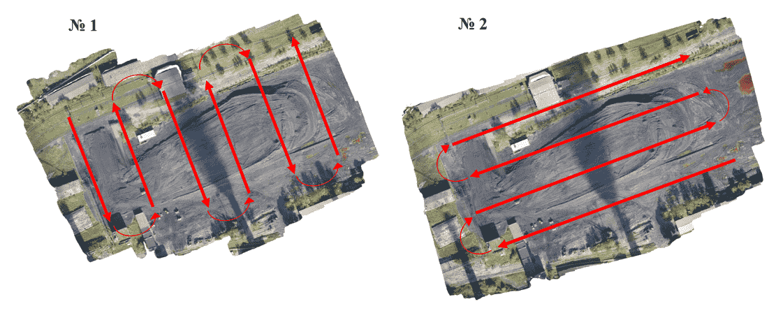
At the stage of preparation for the execution of works, identification signs were prepared in the form of sheets of A3 format with the marked marking in the form of crosses of black color. Then, evenly on the territory of the coal depot, identification marks were placed and the coordinates of their centers were determined with the help of a satellite receiver in RTK mode, to orient the images during processing. The survey was performed by a quadrocopter at an altitude of approximately 100 m. Two UAVs were performed. For research purposes, the flight routes were different (the first flight was made along the warehouse, while the second one – along), for further comparison of the models built between them. The route of the drone flight is shown in Figure 2.
As a result of the shooting, sets of images were received, according to the results of the flight number 1, 68 digital images of the coal depot were obtained, and as a result of the performance of the flight No. 2 99 pictures were obtained. Figure 3 shows the overlapping areas of the images based on the results of the shooting of the 1st and 2nd flights.
On board the quadrocopter is a GPS receiver. At the moment of photographing, the on–board computer records the coordinates of the camera's position in space. These data are further used in the processing. The measurements of the surface of the warehouse using a satellite receiver were also performed, the survey totals 252 pickets, which are evenly located on the surface of the warehouse and repeat the characteristic changes in the relief. This survey was performed to construct a three–dimensional surface from the RTK survey data and to evaluate the models obtained in the photogrammetric way.
6. Finding the parameters of a non–metric chamber and determining their influence on the accuracy of constructing a three–dimensional model.
6.1 Finding the parameters of a non–metric chamber, distortion.
The calibration of cameras consists in determining the values of the internal orientation elements of the camera and the systematic errors of the optical system caused mainly by the distortion of the lens.
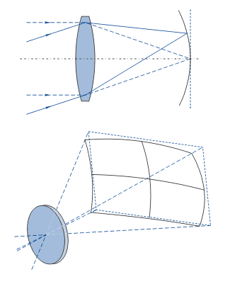
Distortion is the aberration of optical systems, in which the linear magnification changes along the field of view. Light rays, passing through the center of the lens, converge at a point farther from the lens than the rays that pass through its edges [5]. An example of the scheme for the appearance of distortion is shown in Pic. 4.
Elements of internal orientation are the focal length (f) and the coordinates of the main point of the image (xo, yo).
Systematic errors of the optical system determine the differences between the real physical system and its mathematical model. Distortion of the lens affects the geometry of the central design, and as a consequence the principle of collinearity is not fulfilled (the central projection of the image is violated).
There are two types of lens distortion: radial and tangential. The radial distortion is much higher than the tangential, so, as a rule, only radial distortion is determined.
For modern digital cameras, the main problem is the low quality of the lens manufacturing, associated with great distortion and not centering of individual elements of the lens, which leads to non–perpendicularity of the main optical ray to the image plane. Therefore, when calibrating such cameras, it is expedient to determine not only the radial distortion, but also the decentralization of the optical system (non–centered or tangential distortion of the objective).
There are three methods for calibrating cameras:
Calibration with a multi–calibrator calibrator.
Calibration with test object.
Self–calibration.
Self–calibration is a method for calibrating the camera, which allows you to determine the calibration parameters in the process of phototriangulation performed from real–image shots. Self–calibration of cameras, which consists in finding the matrix of internal parameters of the camera using several images of the same scene registered by it. Knowledge of the calibration matrix is necessary for the subsequent determination of the camera position, that is, the external parameters of the camera.
The problem is that the focal length of the camera is known approximately, and there is no distortion parameter.
Depending on the principle underlying the measurement of the coordinates of the points of the photographs, photogrammetric systems can be divided into two large groups: systems based on monocular and stereoscopic measurements of the coordinates of the image points. The systems of the first group are intended primarily for studying objects at individual points marked on the surface of an object or at points that are distinct contours. Systems of the second group are used to build a digital model of an object based on stereo– measurements (automated or interactive) at any points of the surface of the object.
In turn, photogrammetric systems based on monocular measurements of the coordinates of image points can also be divided into two groups. It's interactive and automatic.
Interactive systems. In these systems the object is removed, as a rule, by one camera from different points of photography. As a result, a series of convergent (in the general case) images is obtained. Measurements of the coordinates of image points (reference, binding and determined) are performed monocularly in an interactive mode, and the identification of the corresponding points in the images is performed by the operator. As a result of phototriangulation by the method of ligaments, the elements of the external orientation of the images and the coordinates of all the points of the network are determined. If it is required to perform the measurement of additional points of the object, then their coordinates are obtained as a result of solving a direct multiple photogrammetric intersection using elements of the external orientation of the photographs determined by the phototriangulation.
6.2 Processing of images, construction of a three–dimensional model.
Agisoft PhotoScan was selected for processing. Agisoft PhotoScan is a professional tool for photogrammetric conveyor. It is a stand–alone software product that performs photogrammetric processing of digital images and generates three–dimensional spatial data for use in GIS applications, cultural heritage documentation, for producing visual effects, as well as for indirect measurements of objects of different scales.
The program automatically determines the following calibration parameters for the camera:
fx, fy – focal length;
юx, юy – coordinates of the main point;
K1, K2, K3, P1, P2 – are the coefficients of radial deformation (distortion).
The work on creating the model is carried out in three stages:
1. Determination of the parameters of external and internal orientation of cameras. Loading of photo snapshots is performed and the correspondences in the pictures are indicated, that is, markers are placed on the location of the identification marks with known coordinates. At this stage, PhotoScan finds common points of photos and on them determines all camera parameters: position, orientation, internal geometry (focal length, distortion parameters, etc.). The results of this stage are a sparse cloud of common points in 3D model space and data on the position and orientation of the cameras [4], [6].
In PhotoScan, a sparse point cloud is not used in further processing stages (except the model mode based on a sparse point cloud), and serves only to visually evaluate the quality of photo alignment.
Data on the position and orientation of the chambers is used in further processing stages.
2. Construction of a dense cloud of points. In the second stage, PhotoScan builds a dense cloud of points based on the camera positions and photographs used in the first stage of processing. Before moving to the next stage of creating a 3D model or before exporting a model, a dense cloud of dots can be edited and classified. In this paper, there was the task of editing a dense cloud of points, since in the manual mode it was necessary to exclude the area with machinery (excavator), a transportation bunker and a heating main.
3. Construction of a polygonal model of the object. In the third stage, PhotoScan builds a three–dimensional polygonal model that describes the shape of the object, based on a dense cloud of points. It is also possible to quickly build a model based on only a sparse point cloud. PhotoScan offers two basic algorithmic methods for constructing a polygonal model: A heights map – for flat surfaces (such as terrain or bas–relief) and Arbitrary – for any types of surfaces [6]. The animated figure 5 shows a three–dimensional model of a coal warehouse without taking into account the calibration of the camera and applying the texture based on the results of the voyage ╣ 1.
All models operate for a camera with a central projection. The Brown model is used to describe nonlinear distortions. The distortion model describes the transformation of the point coordinates in the camera's local coordinate system into coordinates in pixels of the frame.
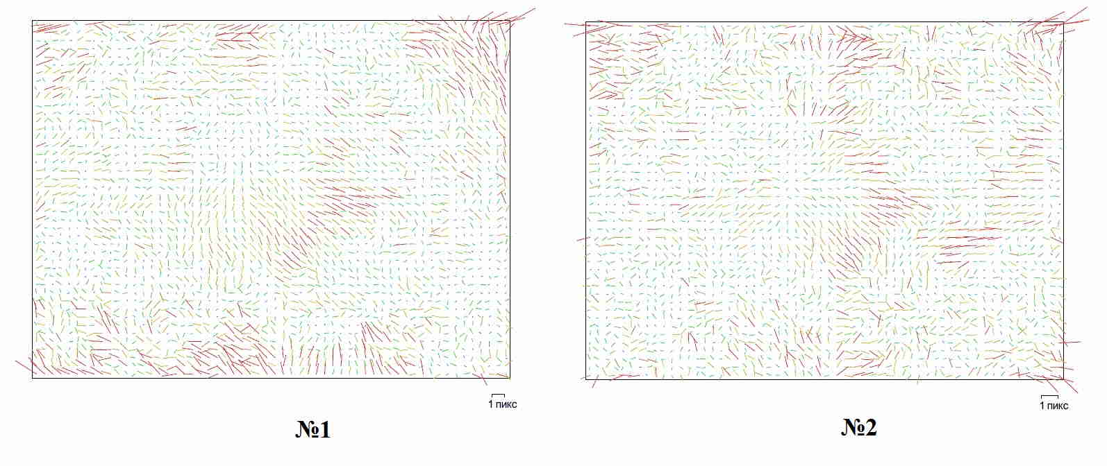
After the calibration of the camera, a result was obtained in the form of residual vectors along the tie points for the camera Zenmuse X5S based on the results of the flight No. 1 and the flight No. 2 in ╨icture 6.
╨icture 7 shows a three–dimensional model of the warehouse, constructed after the calibration of the camera based on the results of the flight number 1.
On the three–dimensional model in Figure 6, a texture is applied for better perception of the model.
6.3 Comparative analysis of surfaces.
After processing the data in the software product PhotoScan, we are able to perform a comparative analysis of the data [7]. The data are placed in Table 1, for clarity and convenience of analysis of the data obtained.
Table 1. Summary table of the results of processing digital images in the software product PhotoScan.
|
|
Flight ╣ 1, without calibration |
Flight ╣ 1, including calibration |
Flight ╣ 2, without calibration |
Flight ╣ 2, including calibration |
|
Number of images, pcs. |
68 |
68 |
99 |
99 |
|
Flight altitude, m. |
104 |
104 |
99.6 |
99.6 |
|
Coverage area, sq. M. |
6.57e+04 |
6.57e+04 |
7.03e+04 |
7.03e+04 |
|
Effective overlapping |
7.9152 |
7.9152 |
9.9289 |
9.9289 |
|
The focal length (Fx, Fy) |
4035.8 |
4035.64 |
4012.8 |
3994.83 |
|
4035.8 |
4035.64 |
4017.19 |
3994.83 |
|
|
The coordinates of the principal point (Cx, Cy) |
2294.82 |
2295.05 |
2400.24 |
2354.98 |
|
1769.18 |
1769.34 |
1817.16 |
1731.47 |
|
|
The coefficients of radial deformation (K1, K2, K3, K4, P1, P2) |
0.00456 |
0.00451 |
0.00113 |
0.00195 |
|
–0.00499 |
–0.00437 |
0.00375 |
0.00046 |
|
|
0.01639 |
0.01531 |
0.00273 |
0.00324 |
|
|
0 |
0 |
0 |
0 |
|
|
0 |
0 |
0.00177 |
0 |
|
|
0 |
0 |
0.00292 |
0 |
|
|
Marker detection error |
0.114 ь |
0.114 ь |
0.126 ь |
0.055 ь |
|
1.47 яшъё |
1.47 яшъё |
1.30 яшъё |
1.20 яшъё |
|
|
Number of points (sparse cloud), pcs. |
25 547 |
25 722 |
31 261 |
31 261 |
|
Number of points (dense cloud), pcs. |
11 414 191 |
11 382 426 |
14 078 509 |
13 376 561 |
|
Number of polygons (3D model), pcs. |
178 595 |
179 708 |
218 223 |
216 371 |
It can be seen from Table 1 that as in the case of the calibration of the chamber of the 1st and 2nd flights, the parameters of the distortion are reduced. Also, analyzing the data, we can say that a large number of polygons in a 3D model can more accurately repeat the surface of a warehouse than, for example, a survey performed by traditional methods.
Conclusions
We can conclude that self–calibration affects the construction of a three–dimensional model. At the moment, work is continuing on the implementation of research work. The calculation of the volumes of the surfaces obtained is performed. The next step will be the analysis of the effect of the camera's self–calibration on the accuracy of the 3D model construction and the formulation of the quality of the camera self–calibration, as well as the writing of the conclusion about the suitability of this method for its implementation in geodetic production.
Bibliography
1. ╦єэ╕т └. └. ╬сюёэютрэшх Єхїэюыюушш эрчхьэющ ЎшЇЁютющ ёЄхЁхюЇюЄюуЁрььхЄЁшўхёъшї ё·хьъш // ─шёёхЁЄрЎш эр ёюшёърэшх єўхэющ ёЄхяхэш ърэфшфрЄр Єхїэшўхёъшї эрєъ. ╩шхт – 2008. –19 ё.
2. ╥■Їышэ ▐. ╤. ╘юЄюуЁрььхЄЁш – тўхЁр , ёхую фэ ш чртЄЁр // ╠шэшёЄхЁёЄтю юсЁрчютрэш ш эрєъш Ёюёёшщёъющ ЇхфхЁрЎшш. ╚чтхёЄш т√ё°шї єўхсэ√ї чртхфхэшщ ╨рчфхы ├хюфхчш ш р¤ЁюЇюЄюё·хьър
╣2. ╠╚╚├└ш╩, ╠юёър: 2011 – 112ё.
3. ╪хтэ ╠. ╤. ╚ёяюы№чютрэшх схёяшыюЄэ√ї ыхЄрЄхы№э√ї ряярЁрЄют фы яюыєўхэш ьрЄхЁшрыют фшёЄрэЎшюээюую чюэфшЁютрэш ╟хьыш // ╬Ёурэ ухюфхчшўхёъшї ёыєцс ёЄЁрэ ╤═├. ═рєўэю Єхїэшўхёъшщ цєЁэры ├хюфхчш ш ърЁЄюуЁрЇш
╣ 1. ╘├┴╙ ╓хэЄЁ ухюфхчшш, ърЁЄюуЁрЇшш ш ╚╧─
, ╠юёър:2013 – 64ё.
4. ├рщёшэ └. ▌., ╩юЁ°єэют ╨. └., ╦хтшЄёър ╬. ═., ═юёъют ┬. ┬., ╧юуюЁхыют ┬. ┬., ╤ъЁ сшэ ╤. ┬., ╘Ёюыют ═. ┬. ╬ЁшхэЄшЁютрэшх ёЄхЁхюярЁ ЇюЄюёэшьъют эр ЎшЇЁют√ї ЇюЄюуЁрььхЄЁшўхёъшї ёЄрэЎш ї яю ъююЁфшэрЄрь юяюЁэ√ї ьхЄюъ // ╬Ёурэ ухюфхчшўхёъшї ёыєцс ёЄЁрэ ╤═├, ═рєўэю Єхїэшўхёъшщ цєЁэры ├хюфхчш ш ърЁЄюуЁрЇш
╣ 7. ╘├┴╙ ╓хэЄЁ ухюфхчшш, ърЁЄюуЁрЇшш ш ╚╧─
╠юёър: 2014 – 64ё.
5. ╩рышсЁютър ърьхЁ // [▌ыхъЄЁюээ√щ ЁхёєЁё], ╨хцшь фюёЄєяр: https://studfiles.net/preview/3557133/page:5/, ─рЄр яюёх∙хэш 11.12.2017 у.
6. ╨єъютюфёЄтю яюы№чютрЄхы Agisoft PhotoScan Professional Edition тхЁёш 1.2, 2016у, 119 ё. // [▌ыхъЄЁюээ√щ ЁхёєЁё], ╨хцшь фюёЄєяр: http://www.agisoft.com/pdf/photoscan–pro_1_2_ru.pdf, ─рЄр яюёх∙хэш 10.12.2017 у.
7. ╩рфэшўрэёъшщ ╤. └. ╬сюёэютрэшх ЄЁхсютрэшщ ъ ЎшЇЁютющ ьюфхыш Ёхы№хЇр, шёяюы№чєхьющ т ёютЁхьхээ√ї Єхїэюыюуш ї р¤ЁюЇюЄюЄюяюуЁрЇшўхёъющ ё·хьъш // ╠шэшёЄхЁёЄтю юсЁрчютрэш ш эрєъш Ёюёёшщёъющ ЇхфхЁрЎшш, ╚чтхёЄш т√ё°шї єўхсэ√ї чртхфхэшщ ╨рчфхы ├хюфхчш ш р¤ЁюЇюЄюё·хьър
╣2. ╠╚╚├└ш╩, ╠юёър: 2013 – 126 ё.