
Содержание
- Introduction
- 1. Relevance of the topic
- 2.Researches
- 2.1 Increased resistance test
- 2.2 High voltage test
- 2.3 The method of partial discharge
- 2.4 Expert system
- Summary
Introduction
Various methods of control of isolation of electric equipment, and in particular isolation of the stator of the generator are considered. The proposed criteria, according to which is determined by the condition of the insulation and the fate of its operation in a particular installation. Offers a comprehensive solution to the control of insulation, methods of prevent the occurrence of insulation defects.
Keywords: isolation, generator, partial discharge method, resistance, voltage.
1. Relevance of the topic
To date, most power plants in the former Soviet Union and Western countries are thermal. As you know, most power plants, except for nuclear power plants, are equipped with generators. The operation of the generator is accompanied not only electricity generation, but also maintenance of the generator, the control of various parameters, identification of defects and their elimination, etc. In my master's thesis discusses the methods of insulation monitoring of generator stator, and in particular, software solutions that allow you to comprehensively assess the condition of generator insulation. It should be noted that today a considerable number of ways of the solution of this problem are offered. However, all modern innovative solutions are based on classical techniques, such as partial discharge method, insulation resistance measurement, insulation voltage measurement.
2. Researches
2.1 Increased resistance test
During the master's work has been studied many techniques. Let's start with the classic. Consider the method of assessing the state of insulation using resistance. During repair or diagnostics, the insulation resistance of the winding of each vase or parallel branch of the stator winding is measured when connected to the housing of all other branches and phases (Fig1). It is worth noting that the generator insulation resistance of the stator winding does not have any normalized values, the readings obtained from the current measurements are always compared with the indicators that were relevant to today's insulation tests. However, there is a limit in the form of R60=Unom∗(1000+0.01∗Snom) whose value must not be less than 0.5 MW.
For example, consider measuring the insulation resistance of the stator winding of a turbogenerator with direct water cooling.
Resistance measurement takes place without water. Measurements are made using a DC voltmeter with an internal resistance of 50 – 100 ohms, which measure the voltage between the contact rings. On past this, in the stator are thermoindicators, which can often be damaged, so to determine their condition, perform a measurement of the insulation resistance of thermoindicators with respect to the housing of 250 – 500 V. in this case, the resistance should be at least 0.5 – 1 MW.
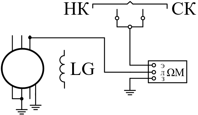
Figure 1–Phases of generator stator winding with direct cooling
An indicator of the state of insulation is the absorption coefficient. At a temperature of 15 –30 ℃ for wetted windings, this ratio is within 1.2 – 2. The coefficient of wetted windings is close to one.
2.2 High voltage test
During the diagnosis of the generator before commissioning, a check of the stator or rotor winding with increased voltage is used, due to the fact that there are insulation defects that can not be detected by checking the increased resistance or visual inspection. The exact magnitude of the increased voltage is determined by parameters such as power, voltage, type of cooling system, design and other parameters. The stator winding is tested with an increased AC voltage of 50 Hz, equal to 1.5 – 2 Unom within 1 minute after stopping the machine. The test is carried out in a hot state and before cleaning from dirt. Also, as an additional test, the rectified voltage equal to 2.5 – 3 Unom is checked for 1 min. The advantages of the rectified voltage test lie in the higher efficiency of controlling the insulation of the frontal parts due to a more uniform distribution of the test voltage on their surface, as the advantage of this method can be attributed to the identification of potential defects at an early stage of development.
Using the test circuit of the generator stator winding with increased AC voltage, shown in Fig.3, we will analyze the measurement process step by step.
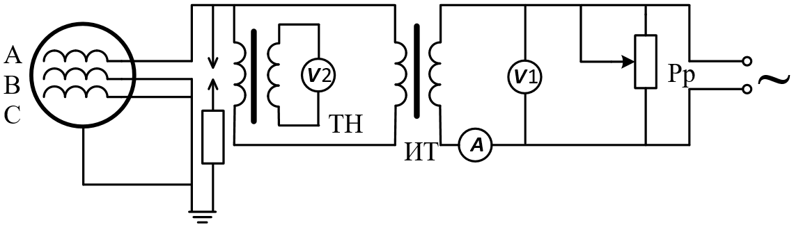
Figure 2 – СArrangement for testing of generator stator winding with a high voltage alternating current
The line voltage Ul=380 V is applied to the step-up test transformer.the rheostat Pp acts as the regulator of this voltage, the operation of which is displayed on the voltmeter V1. RZ spark gap spark gap is used to prevent the increase of the test voltage above the permissible value. This discharger operates with a voltage exceeding the test voltage by 10%. Since the line voltage was applied, a rectified current of considerable magnitude flows through the circuit of the test device. This current consists of the charging current and the absorption current. The geometric parameters of the winding insulation and its location have a strong influence on the value of the charging current. In turn, the absorption current arises from–for the redistribution of charges between the internal inhomogeneous layers of insulation. Since the current supply to the circuit within 2 – 3 minutes leakage current, depending on the minimum humidity and other factors reaches a steady state. In the presence of any defects in the insulation, the current flowing through it changes the rate of its fall. A comparison of the current between the phases can characterize the status of the insulation. The most obvious sign of the presence of defects in the insulation is a large difference between the leakage currents in phases. Usually the difference of 1.5 times between the leakage currents in the phases indicates that there are defects in the insulation, subject to immediate elimination.
There is also a test method for high AC voltage, but there are differences applicable to water-cooled generators. The entire test period must be accompanied by a continuous circulation of water in the stator winding, otherwise the water temperature will rise to 95 ℃ and cause damage to the seals of the windings collectors.
2.3 partial discharge Method
Any assessment of the condition of the equipment on the quantity of the monitored parameters can be performed only on the basis of comparison of data and their direct comparison, and the fresh data obtained from the measurements should be compared with the reference data, which are usually threshold values. Thresholds should integrally reflect the changes of the categories of quality equipment. Quantitative values of thresholds are considered normalized and act as a reference standard for different types of electrical equipment.
the partial discharge Method itself does not provide standard normalized values. However, there are local normalized values and recommendations inherent in different types of electrical equipment. Based on these nuances, a quantitative assessment of the insulation condition of the same generator can be carried out only on the basis of a comparison of recent measurements and measurements of past tests. I. e. it should be said that the state of isolation is not evaluated for one test as a whole, but the dependence of its state on time is traced by collecting the readings of the controlled parameters in different periods of time. In the end, the dependence of the change of such parameters on time is formed, which is called a time trend.
this measurement technique is suitable for a variety of equipment, and any diagnostic method, including the method of partial discharges, which makes this method of measurement universal.
the use of a time trend to assess the condition of the equipment by partial discharges provides for the correct choice of design parameters inherent in a particular equipment.
Partial discharge measured in PC. The PC is determined by the charge, which carries each pulse of the partial discharge. It is worth noting the fact that sometimes partial discharges are measured in mV. However, the use of mV is not fully possible in the time analysis due to the fact that in this type of measurement can be removed only one specific characteristic of the pulse of a partial discharge, but it is impossible to fix other pulses in the same defective zone and in other areas of isolation, if several defects. As practice shows, a large number of pulses with a short amplitude causes more significant damage to the insulation of electrical equipment than single pulses with a larger amplitude.
2.3 partial discharge Method
Any assessment of the condition of the equipment on the quantity of the monitored parameters can be performed only on the basis of comparison of data and their direct comparison, and the fresh data obtained from the measurements should be compared with the reference data, which are usually threshold values. Thresholds should integrally reflect the changes of the categories of quality equipment. Quantitative values of thresholds are considered normalized and act as a reference standard for different types of electrical equipment.
The partial discharge Method itself does not provide standard normalized values. However, there are local normalized values and recommendations inherent in different types of electrical equipment. Based on these nuances, a quantitative assessment of the insulation condition of the same generator can be carried out only on the basis of a comparison of recent measurements and measurements of past tests. I. e. it should be said that the state of isolation is not evaluated for one test as a whole, but the dependence of its state on time is traced by collecting the readings of the controlled parameters in different periods of time. In the end, the dependence of the change of such parameters on time is formed, which is called a time trend.
This measurement technique is suitable for a variety of equipment, and any diagnostic method, including the method of partial discharges, which makes this method of measurement universal.
The use of a time trend to assess the condition of the equipment by partial discharges provides for the correct choice of design parameters inherent in a particular equipment.
Partial discharge measured in PC. The PC is determined by the charge, which carries each pulse of the partial discharge. It is worth noting the fact that sometimes partial discharges are measured in mV. However, the use of mV is not fully possible in the time analysis due to the fact that in this type of measurement can be removed only one specific characteristic of the pulse of a partial discharge, but it is impossible to fix other pulses in the same defective zone and in other areas of isolation, if several defects. As practice shows, a large number of pulses with a short amplitude causes more significant damage to the insulation of electrical equipment than single pulses with a larger amplitude.
it would be more correct to analyze the presence of partial discharges in the insulation on the basis of energy parameters. Energy parameters include quantitative characteristics, as well as allow you to see the energy of each individual pulse. Physically, at each pulse of a partial discharge, an apparent charge is additionally injected from the source of the test voltage into the controlled object, while such a charge is injected into the controlled object instantly and depends on the phase angle of the supply voltage of the network. This suggests that the amount of energy additionally introduced into the equipment and released in the defect zone is equal to the charge multiplied by the instantaneous value of the applied voltage.
the Total energy of partial discharges is calculated as the sum of all pulses. If this energy is divided by the total summation time, we obtain the power of partial discharges, or in other words, the loss of energy into partial discharges:
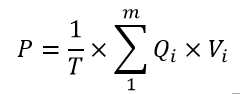
где P – discharge power, W;
Т – time of observation, с.;
M – the number of observed pulses in the time Т;
QiVi – energy i–th pulse's.
Some standards contain an energy parameter under a different designation, namely as PDI & ndash;Partial Discharge Intensity, which means as the intensity of partial discharges. This parameter provides only the same operating voltage for all pulses. Practice has shown that the error between the two parameters in different standards is not more than 20%. This error is considered optimal for the evaluation of the insulation condition.
the PDI Parameter refers to a group of basic parameters used to estimate the intensity of partial discharges in a controlled object. The main criterion, characterizing the rate of development of defects in the insulation, it is a trend change in the parameter PDI. If the value of PDI keeps the value of const within the entire measurement interval, we can talk about the serviceability of the insulation of the electrical machine. If const is not preserved, then insulation should be considered for defects.
the Quantitative estimate is always relative. Its use makes limited possible the absence of reliable and universal criteria, quality thresholds. Only the presence of a pronounced tendency to increase the intensity of partial discharges can serve as a reliable sign of the presence of dangerous and developing defects in the insulation of an electric machine.
2.4 Expert systems
An Example of a system for monitoring partial discharges in the insulation of the winding to such a system can be attributed to the MDR system from the brand DIMRUS. To be more precise, the full name of this system is MDR & ndash;3 / UHF. The system works on the basis of high-frequency current transformers. One of the advantages of this system is easy installation, and the disadvantages include a relatively low sensitivity. It is worth noting that the above advantages and disadvantages are determined by the types of partial discharge sensors. To increase the overall level of sensitivity of the system, the function of connection of measuring capacitors was implemented. Communication capacitors significantly increase the sensitivity of the system to defects, even if the defective place is far away from the sensor. The high sensitivity of such sensors is due to the fact that they are the most low-frequency sensors of all used for the registration of partial discharges. The lower the frequency, the less attenuated the signal at the tooth-slot structure of the stator.
- the first distinguishing feature of MDR–3/UHF is the presence of registration equipment. Such equipment operates in the frequency range from 0.5 to 1500 MHz. The registration equipment allows the expert system under study to record insulation defects both inside the grooves and in the frontal parts with maximum sensitivity.
- the Second advantage is the use of electromagnetic antennas as CR sensors. This antenna is a conductor in high-voltage insulation, laid on the circumference of the stator in the area of the windings. The antenna is simple in design, reliable, has no galvanic connection with the windings of the machine, which occurs when using communication capacitors. In addition, the use of electromagnetic antennas makes it possible not to disconnect the communication capacitors if high-voltage stator tests are carried out.
Figure 3 – System MDR–3/UHF"
(animation: 10 frames, 5 cycles of repetition, 27,1 kbps)
- The Third feature is that the electromagnetic antenna installed on the frontal parts of the stator winding provides the same sensitivity to defects in all phases and sections of the stator winding, it also allows to register the CR in the rotor winding, this is due to the fact that the antenna is located at a short distance from all windings. In addition, since the maximum distance from the place of occurrence of partial discharges to the annular antenna does not exceed half the length of one conductor laid in the stator groove, the electromagnetic antenna has a high sensitivity to these defects. Using the time difference between the arrival of pulses to the frontal parts of the winding, it is possible to determine the location of the insulation defect in the stator groove.
- The Fourth feature is that the electromagnetic antenna is protected by metal covers that completely cover all the front parts of the electric machine. This solution made it possible to make the antenna insensitive to high-frequency interference that appears from the outside by electromagnetic means.
Summary
Conclusion. At the time of writing this abstract, the master's work has not been completed and in the future provides for the calculation of the behavior of the generator isolation model in various modes of operation. The main methods for insulation control were described, various solutions from commercial organizations were proposed, such solutions are based on the method of partial discharges and are based on classical techniques in combination with modern computing SOFTWARE and sensors.
Source list
- Профилактические испытания изоляции оборудования высокого напряжения, Бажанов С.А., М., ЭНЕРГИЯ, Москва 1968 г.,72 с.
- Обслуживание электрических подстанций/ О.В. Белецкий, С.И. Лезнов, А.А Филатов. – М.: Энергоатомиздат, 1985, – 416 с.
- Обслуживание генераторов, Чернев К.К. – М.: Энергоатомиздат, 1989 г., 592 с.
- Электрические системы и сети, Идельчик В.И. Учебник. – М.: Высшая школа, 2003. – 463 с.
- Электрические машины, Кацман М.М. Учебник. – М.: Высшая школа, 2003. – 463 с.
- Рожкова Л.Д., Козулин В.С., Электрооборудование станций и подстанций 3–е изд., перераб. и доп. Учебник для техникумов. М.: Энергоатомиздат, 1987. – 648 с.
- Неклепаев Б.Н. Электрическая часть электростанций и подстанций. Учебник для вузов – 2–е изд. М. Энергоатомиздат, 1986. – 640 с.
- Сайт компании
DIMRUS
Измерение частичных разрядов в изоляции статоров высоковольтных электрических машин [Электронный ресурс] – Режим доступа: Компания DIMRUS – (дата обращения: 15.10.18). - Сайт компании
DGM KZ
Краткая информация о частичных разрядах (ЧР) и их измерении [Электронный ресурс] – Режим доступа: Компания DGM KZ – (дата обращения: 17.10.18). - Выдержка из книги Бажанов С.А. Профилактические испытания изоляции оборудования высокого напряжения [Электронный ресурс] – Режим доступа: Большая энциклопедия нефти и газа – (дата обращения: 14.11.18).
- Выдержка из книги Бажанов С.А. Профилактические испытания изоляции оборудования высокого напряжения [Электронный ресурс] – Режим доступа: Большая энциклопедия нефти и газа – (дата обращения: 10.12.18).
- Сушка изоляции генераторов [Электронный ресурс] – Режим доступа: Электронный ресурс KazEDU – (дата обращения: 16.12.18).