
Abstract
Content
- Introduction
- 1. Theme urgency
- 2. The goal of the master's work
- 3. Purpose, composition and schemes of the thyristor converters
- 4. Thyristor control pulse formers
- Conclusion
- References
Introduction
Semiconductor rectifier units are widely used in various industries, railway transport, airplanes etc. They are used to power the electrolysis processes in non-ferrous metallurgy and chemical industry; to power the electric drive system of DC motors for various purposes and power; for the excitation of large electric generators; for traction substations and mainline electric locomotives of alternating current and to meet many other needs of the national economy.
The production and distribution of electrical energy is mainly carried out on alternating current. At the same time, much of the electricity is consumed in the form of direct current. This is due to the fact that some consumers can only operate on direct current. Another part of consumers has the best characteristics and parameters of direct current.
At the present, semiconductor converters of electrical energy are almost exclusively used to convert AC to current – rectifiers.
Significant progress in converter technology is associated with the creation of power semiconductor valves. High electrical parameters, small dimensions and weight, simplicity of design and maintenance, high operational reliability of semiconductor valves make it possible to widely use them in AC-to-DC conversion circuits.
The capabilities of the converters are significantly expanded with the development and use of thyristors. Thyristor rectifiers provide a deep change in output parameters in any desired range; possess high speed and accuracy of automatic control; allow you to convert the inverter into inverter mode and thereby ensure the recovery of electricity into the network.
The above qualities of thyristor converters make them very promising devices for powering DC electric drive systems with a smooth rotation frequency control over a wide range, for exciting large electric generators and other purposes. [1].
1. Theme urgency
At the present, much attention is paid to the development of semiconductor converters for regulating the speed of asynchronous, synchronous, step, valve, valve-inductor and other types of electric motors.
Despite this, the task of creating a thyristor converter for a direct current electric drive (ED) has not lost its relevance. So, even now, in many industries, DC electric current is widely used. Therefore, there is no reason to assert that in the near future there will be a complete replacement of the DC drive by the AC drive.
Abroad, such well-known companies as Siemens, ABB, Emerson and many others have achieved great success in the development of thyristor converters for direct current drives. However, the use of the results of their development in this area is almost impossible due to the secrecy of information [2].
That is why the master's work is devoted to the actual scientific task of developing a power scheme of a thyristor converter.
2. The goal of the master's work
The goal of the master's work is the development and study of the power scheme of a thyristor DC voltage converter, the development of a scheme and a pulse former board for controlling thyristors and finding ways to optimize the current consumption from the power source by this device.
3. Purpose, composition and schemes of the thyristor converters
An electric drive based on thyristor converters is currently the main type of industrial controlled electric drive of constant current. This is due to a number of advantages of this type of electric drive, the main of which are as follows:
- fast response, which is limited by the switching capacity of the motor and the mechanical inertia of the drive;
- readiness for operation, wide temperature range and long service life;
- the nominal efficiency of the converter exceeds 92–96%;
- low weight and size indicators; block configuration allows to reduce the required production area, reduce capital, installation and operating costs.
At the same time, the thyristor drives are characterized by disadvantages:
- pulsations of rectified voltage and current at the output of the thyristor converter increase the heating and worsen the switching of the motor, which requires the installation of smoothing chokes;
- at deep regulation voltage thyristor converter has a low power factor that requires the development and installation of special compensating devices;
- the overload capacity of the thyristor converter is lower than that of the electric machine;
- during operation of thyristor converters, the form of voltage in the AC mains is distorted, and interference occurs.
By purpose thyristor converters are divided:
- to power the motor armature;
- to power the excitation windings;
By the execution of the thyristor are divided:
- irreversible;
- reversible;
The most effective for thyristor converters is recognized as a three-phase bridge (six-pulse) rectification scheme (fig. 1) [3 p. 11–12].
Because it has a number of advantages, such as:
- the minimum rated power of the transformer, the transformer operates in good mode, there is no flow of forced magnetization;
- the smallest reverse voltage on the valve;
- the largest rectified voltage at the same phase;
- small pulsations;
- possibility of using a transformerless scheme.
And a slight disadvantage: double the voltage drop on the valves, which is especially important at low voltages [4 p. 120]
It is the three-phase bridge rectification scheme for the irreversible thyristor converter that will be used in this work.
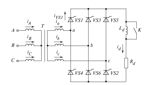
Figure 1 – Three-phase bridge rectifier
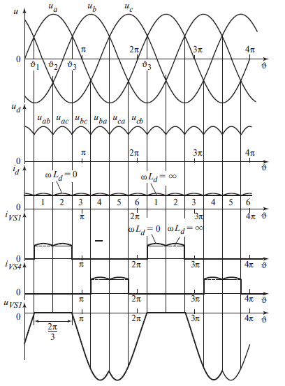
Figure 2 – Current and voltage diagrams of three-phase bridge rectifier at an angle α= 0
Consider the principle of the circuit (fig. 1) with the active nature of the load (key K is closed). Starting from the moment ν1 the thyristors VS1 and VS6 conduct current, the other thyristors are turned off. In this case, to the load Rd line voltage applied uab and current id flows through the circuit: winding of phase a – thyristor VS1 – load Rd – thyristor VS6 – winding of phase b. This process in the scheme continues until ν2, that is during the time corresponding to π/3, when the potential of phase b becomes positive. Starting now, the voltage ubc takes a positive value (forward voltage for thyristor VS2). When the control pulse is applied to the VS2 thyristor at this time, it begins to conduct current, the thyristor VS6 is switched off (switching occurs between the thyristors VS6 and VS2). For turned off thyristor VS6 voltage ubc is reverse. The thyristors VS1 and VS2 are in the conducting state, the other thyristors are turned off.
At the moment ν3 a control pulse is applied to the VS3 thyristor and it turns on. The thyristor VS1 is switched off so that the potential of phase b becomes higher than the potential of the phase a. Then the following thyristor pairs are switched at intervals equal to π/3: VS2-VS4, VS3-VS5, VS4-VS6, VS5-VS1. Thus, during the period of the supply voltage, six commutations occur through the interval π/3 each, with three of them – in the cathode group of thyristors VS1, VS3 and VS5 (with combined cathodes) and three – in the anode group of thyristors VS4, VS6 and VS2 (with combined anodes). The numbering of the thyristors in this scheme is not random, but corresponds to the order of their entry into work, subject to the transformer phasing indicated in fig. 1.
Alternately, the operation of different pairs of thyristors in the scheme leads to the appearance of a rectified voltage on the Rd resistance, consisting of parts of the linear voltages of the secondary windings of the transformer (see fig. 2). The switching moments coincide with the moments of passing through zero line voltages (when two phase voltages are equal, for example ua and ub). The duration of the current passing through each thyristor is equal to 2π/3, during the rest of the time, a reverse voltage is applied to it, consisting of parts of the corresponding line voltages [5].
Figure 3 shows the process of rectifying AC voltage to DC voltage occurring in the thyristor converter. AC voltage from the mains acting on the transformer (TV) decreases, then it goes to a controlled rectifier (CR), which is controlled by the control system (CS). At the output of the CR, the alternating voltage becomes a constant pulsating, passing through a smoothing choke (L) is fed to the armature winding of the DC machine М.
Figure 3 – The process of rectification in thyristor converter
(animation: 5 frames, 7 cycles, 61 Kb)
4.Thyristor control pulse formers
The functions of control pulse formers are performed by amplifiers designed to amplify the control information signal into a signal with the parameters necessary for the guaranteed switching on and off of the semiconductor key. In addition to the requirements for the power of the control signal key is often required to the form of the signal, so sometimes called FPC amplifiers – pulse formers control. Circuit design FPC primarily depends on the type of device being controlled and its static and dynamic properties.
If there is a direct voltage on a traditional thyristor, a control impulse is formed. The polarity of the voltage that generates the control current corresponds to a positive voltage on the control electrode of the thyristor relative to the cathode, which corresponds to the forward bias of the control p-n junction.
The parameters of the control current pulse must correspond to the input characteristics of the thyristor. The control pulse must have a high current rise rate and an increased amplitude when switched on. This speeds up the process of switching on and reduces the possibility of thyristor failure due to an increased rate of rise of the anode current. di/dt. After completion of the process of switching on the control pulse, it is desirable to make it equal to zero, since a long pulse increases the power loss in the thyristor. However, it is necessary to take into account that when there is an inductive component in the load, the activation process is delayed, and in this case the pulse must be of an increased duration in order to ensure the thyristor is switched on [6].
Conclusion
As a result of the work done, an electrical circuit diagram of a pulse shaper was developed, and the pulse former was simulated, which resulted in the formation of a technique for reducing the current consumption by the device from the power source. A prototype board has been developed for unlocking a thyristor operating on an active load in the form of an incandescent lamp in asynchronous mode.
This master's work is not completed yet. Final completion: May 2019. The full text of the work and materials on the topic can be obtained from the author or his head after this date.
References
- Vuz-24.ru [Электронный ресурс]. – Режим доступа: http://vuz-24.ru...
- Сергеев Александр Георгиевич. Разработка и исследование тиристорного выпрямителя с микропроцессорным управлением для широкорегулируемого электропривода : диссертация кандидата технических наук : 05.09.12 / Сергеев Александр Георгиевич; [Место защиты: Чуваш. гос. ун-т им. И.Н. Ульянова] Чебоксары, 2007 152 c. : 61 07-5/5255 [Электронный ресурс]. – Режим доступа: http://www.dissercat.com...
- Лалетин В.И. Проектирование тиристорных преобразователей для электроприводов постоянного тока: Учебное пособие. – Киров: Изд-во ВятГУ, 2006. – 131 с.: ил.
- Гельман М.В. Преобразовательная техника: учебное пособие / М. В. Гельман, М. М. Дудкин, К. А. Преображенский. – Челябинск: Издательский центр ЮУрГУ, 2009. – 425 с.
- Справочник по силовой электронике / Ю.К. Розанов, П.А. Воронин, С.Е. Рывкин, Е.Е. Чаплыгин ; под ред. Ю.К. Розанова. – М.: Издательский дом МЭИ, 2014. – 472 с., ил. с. 205-207.
- Розанов Ю. К. Силовая электроника: учебник для вузов / Ю. К. Розанов, М. В. Рябчицкий, А. А. Кваснюк. 2-е изд., стереотипное. – М. : Издательский дом МЭИ, 2009. – 632 с.: ил.
- Datasheet: Pulse Transformer with Double Secondary Winding - Schaffner IT249 [Электронный ресурс]. – Режим доступа: http://www.farnell.com....