
Abstract
Content
- 1. The mechanisms of the bath rotation, lifting and turning the arch with their support on the cradle
- 2. The mechanism of raising the arch
- 3. The mechanism of rotation of the arch
- 4. The mechanism for moving the electrodes
The mechanisms of the bath rotation, lifting and turning the arch with their support on the cradle
Most of the domestic furnaces of this type built in recent decades are similar to the device of a 100-ton furnace, shown schematically in Figure 4. The furnace body (not shown in the figure) rests on cradle 8 through four support bollards 9. The arch 12 is suspended from a semi-portal consisting of two L-shaped racks 14 using chains 11 thrown over the rollers 13. The ends of the chains are connected by a drive 7 (electric motor and worm gearbox with a traction screw), which moves the chains, ensuring the raising and lowering of the roof. Two actuators 7 are connected by a synchronizing shaft 15.
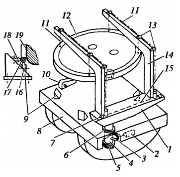
Figure 1 – Mechanical equipment of the furnace with a support for lifting and turning mechanisms on the cradle
The half-portal is fixed on a cast steel swivel plate 1, which at one end is mounted on a rotary shaft 4 with a diameter of 750 mm. The shaft is fixed in the cradle, resting on the thrust bearing 5 and the upper 6 and lower roller bearings. The shaft rotates an electric motor with a gearbox 2 through a bevel gear, which engages with a bevel gear sector 3 mounted on the shaft 4. On the turntable 1 between the L-shaped posts there are three racks of the mechanism for moving the electrodes (figure 4 is not shown).
When the furnace is opened for loading, the drive 7 is turned on, raising the arch by 150-300 mm, and the electrodes are lifted, leading them out of the working space. Next include the actuator 2, turning the shaft 4 at an angle of 80 °; together with the shaft, the plate 1 and the portal, the arch and the electrodes fixed on it, rotate around its axis, opening the working space from above. The mechanism of rotation of the bath is designed to rotate the furnace around the vertical axis by 40 ° in one and the other side relative to the normal position. This allows, during melting at three positions of the casing, nine wells are melted in the charge, which shortens the time of charge melting. The possibility of rotation is ensured by the fact that the furnace body 19, by means of an annular rail 17 attached to it, rests on the rollers 16 of the supporting pedestals 9. One or two rotation mechanisms 10 are mounted on the cradle; each of them consists of an electric motor with a gearbox, the output shaft of which engages with the toothed sector fixed on the furnace body, due to which the rotation of the shaft causes the body to rotate. When you turn on the mechanism 10 and the rotation of the housing ring rail 17 rolls on the rollers 16, and the rollers 18 prevent lateral displacement of the housing. On high-power furnaces, such a mechanism is not necessary, since in the process of melting around three electrodes a common melting zone or well is formed, and not three separate melted wells, typical of low-power furnaces.
The mechanism of raising the arch
The raising and lowering of the roof is carried out by two synchronously operating mechanisms driven by electric motors 25 and worm-screw gearboxes 24. The arch 21 is suspended from the half-portal 19 on the chains 20 and thrusts 4 connected to the worm-screw gearboxes thrown over blocks 5 and 18. During operation of the electric motor 25 and the worm-screw gearbox 24, the drive screw 24a of the gearbox receives translational movement up or down by moving the thrust 4 of the chain 20 and, thus, the roof 21 (to a height of 500 mm). To synchronize the operation of the two mechanisms, an equalizing shaft 31 is provided, which is connected to the gearboxes via couplings 32.
The mechanism of rotation of the arch
For the top of the arch from the working space of the furnace, rotate the shaft 27 with the plate 30 rigidly fixed on it, which is the support of the semi-portal 19 and the arch 21 suspended from it; the rotary shaft 27 is supported on the cradle of the furnace through two radial 29 and one thrust 26 bearings. The rotation drive is an electric motor 22 and a three-stage spur gear 23, on the output shaft of which a bevel gear gear is fitted, which meshes with the gear sector 28 rigidly mounted on the shaft 27. Receiving rotation from the drive, the gear gear causes rotation of the gear sector 28 and the shaft 27 around its vertical axis and, thus, the rotation of the plate 30 and the roof of the furnace.
The mechanism of rotation of the arch
This mechanism is driven by a drum winch, including an electric motor 1, a worm gear 2 and a drum 3. Rotation of the drum causes upward or downward movement of the rope 7, thrown through blocks 10 and through the block 13 fixed on sleeve 15, and thereby vertical movement of the carriage 8 with the sleeve 15, carrying the electrode holder 16 with the electrode 17. The carriage on the rollers 14 moves along the column 6; blocks 10 are called stationary, and moving in a vertical direction, block 13 is movable. Cargo 9 with the help thrown through the blocks 11 of the rope 12 partially balances the gravity of the carriage 8.
References
- Дуговые печи. Учебное пособие для вузов / Свенчанский А. Д., Смелянский М. Я., – М.: Энергия, 1970, – 264 с.
- Электрические промышленные печи. Дуговые печи и установки специального нагрева. Учебник для вузов / Свенчанский А. Д., Жердов И. Т., Кручинин А. М., – М.: Энергоиздат, 1981, – 296 с.
- Короткие сети и электрические параметры дуговых электропечей / Данцис Я. Б., Кацевич Л. С., Жилов Г. М., – М. : Металлургия, 1987, – 320 с.
- Электрические печи сопротивления и дуговые печи / Гутмана М. Б., – 1983, – 360 с.
- Расчёт мощности и параметров электрических печей черной металлургии / Егоров А. , – 1990, – 281 с.
- Атлас. Дуговые сталеплавильные печи, – 1978, – 180 с.
- Металлургические печи / Диамидовский Д. А., – М.: Металлургия, 1961, – 191 с.