
Abstract
Content
- Introduction
- 1. Theme urgency
- 2. Development of computer model of thermal power plant
- 3. Modeling start-up and self-start-up conditions for electric motors of system auxiliaries
- Conclusion
- References
Introduction
Reliable and economical operation of modern thermal and nuclear power plants to a large extent depends on the reliability of the mechanisms of the auxiliaries. The main drive type of the most important mechanisms of auxiliaries power plants are asynchronous and synchronous motors 6 kV. The continuous increase in unit capacity of the blocks leads to an increase in the installed power of the motor load, unit power and inrush currents of the phase asynchronous electric motors (AM), which in some cases makes it difficult to ensure successful self-starting and dynamic stability of the motor load during short circuit and short-term voltage drops. This can lead to emergency shutdown of power plant units and a decrease in the reliability of the operation of the entire power grid as a whole. In some transient modes (switching the power to another source, disconnecting the short circuit and others), shock currents and moments may occur in the motors, exceeding the allowable and significantly reducing their service life.
Currently, there is a practice of using various software products at the design stage (CAD) and operation of energy facilities. However, in the process of operation, there is a need for verification calculations when analyzing accidents, drawing up technical specifications for reconstruction, technical re-equipment. It is proposed to use one computer model for the entire life cycle of a power plant: its design, construction, installation and commissioning of equipment, as well as subsequent operation.
1. Theme urgency
In this case, the electrical part of Zuevskaya TPP-2 was modeled in connection with the reconstruction of the main power supply of the second
lift hatchline. This decision was made to improve the reliability and efficiency of pumping stations. At Zuevskaya TPP-2 a reverse system of
technical water supply with cooling towers was used. In order to replenish significant losses of industrial water, a scheme has been implemented
to feed the industrial water circuit from the Zuyevsk reservoir. The pumping pump of this water of technical water is powered by the
Zuevskaya-110
substation, which is under the jurisdiction of the Khartsyzsk Electric Networks enterprise. Pumping power circuit has low
reliability.
In a similar position, the boom pumping station of the second lift, pumping the ash-slag pulp to the ash dump of the power station, also
turned out to be. The pumping station receives power via two cable lines from Zhilposelok-110
substation, also operated by Khartsyzk Electric
Networks. Due to cable damages with voltages of 6 and 10 kV, the power circuit of this pump also has low reliability.
In order to improve the reliability and efficiency of these pumping stations at ZuTPP, it is envisaged to transfer them from the power supply system power units with voltage of 6 kV. The main task of the work is to determine the technical conditions for the transfer of power to one of these pumping stations. To do this, we investigated the workings of sections of a auxiliaries power units, changes in short-circuit currents in the system auxiliaries power units at various modes of their work[1].
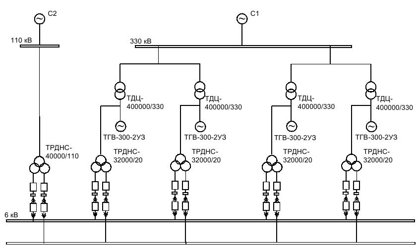
Figure 1 – Diagram of the main electrical connections
2. Development of computer model of thermal power plant
A developed computer model consisting of a graphic image of an electrical circuit, formed in a graphic editor of AutoCAD, and its
accompanying information support, located on sheets of an Excel spreadsheet file [2-3]. In particular, one of them presents the data of
deep-phase AM of the system of auxiliary. The design scheme is made in a two-layer version. In layer 0
, a power distribution circuit is formed,
including generator voltage circuits, step-up block transformers, power transmission lines with a network substation, as well as operating backup
auxiliary transformers. Layer 6
form auxiliaries. Circuit including sections, inputs for working and backup power, backup power bus. Figure 1
shows the graphic component of the computer model of the electrical part of a power plant. The graphic blocks in the form of a dot with a number
(in Fig. 2 are shown in red) are used to identify the electrical units.
Figure 2 – Computer scheme of the issuance of power plant and auxiliary system
During the operation of the power plant, there may be a different number of units in operation. Especially often configured is a 6 kV auxiliary system circuit in connection with the possibility of powering its sections in a solar circuit power units from working or backup transformers of their own needs. Graphic blocks of switches are used in the design scheme to form variants of schemes with different compositions of equipment. Imitation of their switching on the design scheme is carried out by replacing graphic blocks of switched on and off switches.
When calculating the transient electromechanical processes in the system of own needs (start-ups and self-starting AM), to increase the speed of performing the calculations, the equivalence of the whole power output scheme with respect to one of the workers or standby auxiliary transformers was applied. To determine this auxiliary transformers, a software analysis is made of the circuit, starting from the user-selected sections of the auxiliary, their inputs included, and further on up to the auxiliary transformers. In addition, elements not participating in the calculations are excluded from the calculation scheme of the auxiliary needs system. For this purpose, an auxiliary test mode of the power supply of sections of a auxiliary is simulated from the selected auxiliary transformers and then from the circuit are excluded elements whose currents have zero values. The determination of voltages at the nodes of the circuit (Fig. 2) in the calculation of transients is performed by the method of potential difference in the vector-matrix record form. Calculation of the frequency of rotation of aggregates in the start and self-start modes, it is performed by solving the basic equation of motion of their rotors.
Calculations were made of the parameters of equivalent replacement circuits for deep-phase asynchronous electric motors [4]. The initial data of blood pressure and the obtained parameters of their models were recorded on a sheet of the created Excel spreadsheet [5]. In addition, information on the composition of the mechanisms of the auxiliary individual sections of power units.
3. Modeling start-up and self-start-up conditions for electric motors of system auxiliaries
Whis help of computer model of the power plant, calculations of the start-up and self-start modes of the AM have been performed.[6]At the power plant, in order to increase the reliability of the power supply system of the pumping pumping of the second climb, it is planned to change its main power supply circuit from the sections of the auxiliary one of the units. To substantiate this design decision, many variant calculations of the and self-starting mode of the AM were performed. As an example, below, Figure 3 shows the results of calculating the self-start[7] mode of the AM in section 1A of unit No.1 after a power interruption of 2,5 seconds. It shows the curves of changes in rotational frequencies and voltage changes in the process of self-start-up.
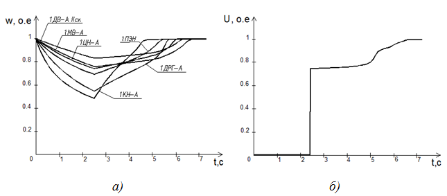
Figure 3 – Changing the frequency of rotation of AM (a) and the voltage on the section (b) in the process of self-start-up
Conclusion
- A computer model of the electrical part of one of the power stations of Donbass has been developed. With its help, calculations of short circuit currents and verification of the main electrical equipment and conductors were carried out, both in the power output scheme and in the auxiliary system with a voltage of 6 kV.
- . The simulation of the start-up and self-start modes of the electric motor of the SN system, which made it possible to select the circuit and mode solutions for the proposed reconstruction of the power supply system of the pumping of the second climb of thermal power plant.
This master's work is not completed yet. Final completion: June 2019. The full text of the work and materials on the topic can be obtained from the author or his head after this date.
References
- Крючков, И. П. Расчет коротких замыканий и выбор электрооборудования: учеб. пособие для студ. учеб. заведений / И. П. Крючков, Б. Н. Неклепаев, В. А. Старшинов и др.; под ред. И. П. Крючкова и В. А. Старшинова. – 2-е изд., стер. – М.: Издательский центр
Академия
, 2006 – 416 с. - Справочник по электроснабжению и электрооборудованию: в 2 т. Под общ. ред. А. А. Федорова. Т 2 Электрооборудование. - М.: Энергоатомиздат, 1987. – 592 с.
- Павлюков, В. А. Разработка САПР электрической части станций и подстанций для учебного процесса / В. А. Павлюков, С. Н. Ткаченко, А. В. Коваленко // Завалишинские чтения'2018, ГУАП, г. Санкт-Петербург, 2018/4–145-153 с.
- Павлюков, В. А. Учебная САПР электрической части станций и подстанций : учеб. пособие / В. А. Павлюков, С. Н. Ткаченко, А. В. Коваленко. – Харьков : ФЛП Панов А. Н., 2016. – 124 с.
- Павлюков, В. А. Совершенствование методов идентификации параметров эквивалентных схем замещения глубокопазных асинхронных двигателей / В. А. Павлюков, С. Н. Ткаченко. – Электричество, 2018. – №10. – С.54-60.
- Сивокобыленко В. Ф. Параметры и схемы замещения асинхронных двигателей с вытеснением тока в роторе /В. Ф. Сивокобыленко, В. А. Павлюков. – Электрические станции, 1976. - №2.
- Павлюков, В. А. Совершенствование методики обработки данных асинхронных электродвигателей в учебной САПР / В. А. Павлюков, В. С. Рудов // Инновационные перспективы Донбасса: материалы III Международной научно-практической конференции. Секция
Перспективы развития электротехнических, электромеханических и энергосберегающих систем
, 24 мая 2017 г., г. Донецк. Т. 2. – Донецк: ДонНТУ, 2017. – С. 35-39.